
Control apparatus for internal combustion engine

A technology for controlling equipment and internal combustion engines, applied in mechanical equipment, engine control, fuel injection control, etc., can solve problems such as the internal combustion engine is not optimal, the fuel injection ratio cannot be delayed, etc., to prevent torque reduction and prevent internal combustion engine torque reduction. Effect

Inactive Publication Date: 2008-03-12
TOYOTA JIDOSHA KK
View PDF1 Cites 6 Cited by
  • Summary
  • Abstract
  • Description
  • Claims
  • Application Information

AI Technical Summary

Problems solved by technology

[0006] However, in order to achieve early warm-up of the exhaust catalyst, the aforementioned fuel injection ratio is the difference between the fuel injection valve (in-cylinder injector) for injecting fuel into the cylinder and the fuel injection valve (in-cylinder injector) for injecting fuel into the intake manifold. Fuel injection valves (intake manifold injectors) for internal combustion engines are not optimal
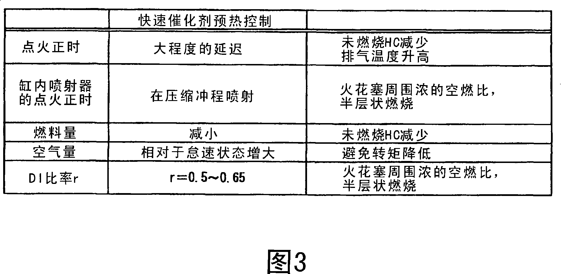
In other words, for the ignition timing which is the most important factor for catalyst warm-up, sufficient retardation cannot be achieved at this fuel injection ratio

Method used


Image

  • Control apparatus for internal combustion engine
  • Control apparatus for internal combustion engine
  • Control apparatus for internal combustion engine

Examples


Embodiment Construction

[0030] Hereinafter, embodiments of the present invention are described with reference to the drawings. In the following description, similar components are denoted by similar reference numerals, and the names and functions of these components are the same. Therefore, its detailed description will not be repeated.

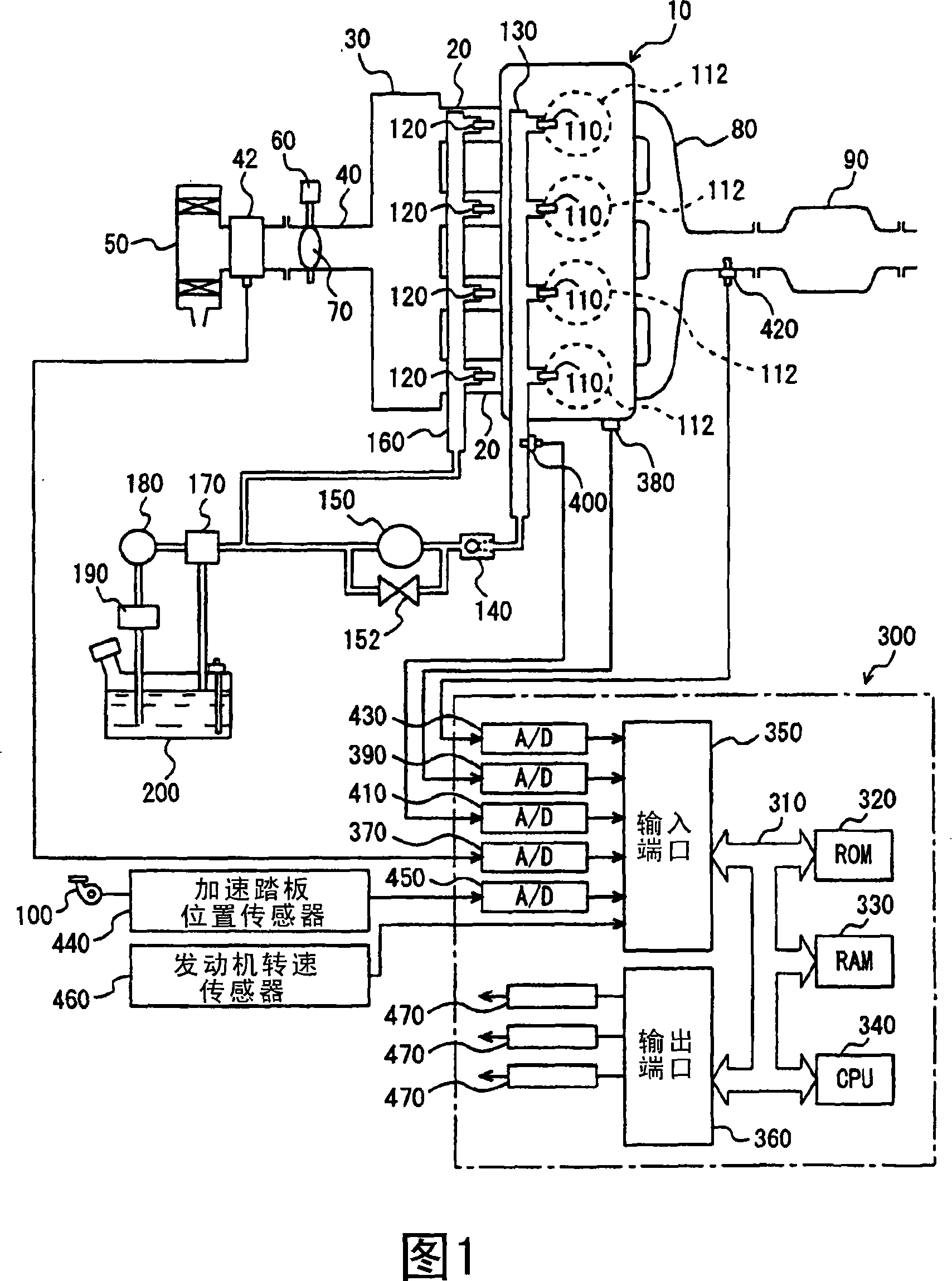
[0031] FIG. 1 is a schematic structural view of an engine system controlled by an engine ECU (Electronic Control Unit), which can be regarded as a control device for an internal combustion engine according to one embodiment of the present invention. Although an in-line four-cylinder gasoline engine is shown as the engine in FIG. 1, the present invention is not limited to such an engine.

[0032] As shown in FIG. 1 , engine 10 includes four cylinders 112 each connected to a common surge tank 30 via a respective intake manifold 20 . The surge tank 30 is connected to an air cleaner 50 via an intake pipe 40 . An airflow meter 42 is arranged in the intake pipe 40 , an...


PUM


Abstract

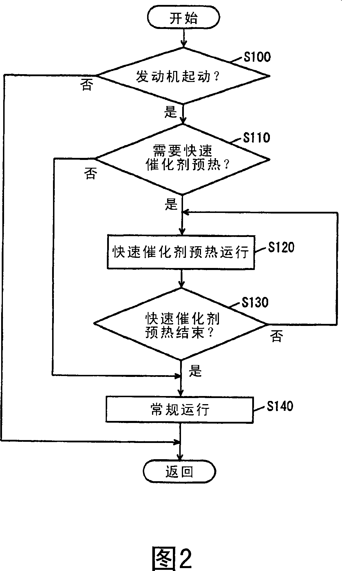
An engine ECU executes a program including the step of performing an operation for rapid catalyst warm-up (S120), under the conditions that an engine is started (YES in S100) and rapid catalyst warm-up is necessary (YES in S110), by setting the ratio of fuel injection by an in-cylinder injector to be equal to or higher than that of an intake manifold injector and retarding the ignition timing to a large degree, and the step of performing normal operation (S140) under the condition that the catalyst is warmed up to be activated (YES in S130).

Description

technical field [0001] The present invention relates to a control apparatus for an internal combustion engine comprising a first fuel injection mechanism (in-cylinder injector) for injecting fuel into a cylinder and a first fuel injection mechanism (in-cylinder injector) for injecting fuel into an intake manifold or intake port Second fuel injection mechanism (intake manifold injector). Specifically, the control apparatus for an internal combustion engine according to the present invention is used in the case of rapidly warming up a catalyst for purifying exhaust gas. Background technique [0002] A known type of internal combustion engine includes an intake manifold injector for injecting fuel into the engine's intake manifold and an in-cylinder injector for injecting fuel into the engine's combustion chambers, as determined by engine speed and engine load. [0003] Japanese Patent Laid-Open No. 11-324765 discloses a control apparatus for a direct-injection spark ignition ...

Claims


Application Information

Patent Timeline
Patent Type & Authority Applications(China)
IPC IPC(8): F02D41/02F02P5/15
CPCF02D37/02F02P5/1502F02D41/0255F02D41/3094Y02T10/26Y02T10/46Y02T10/12Y02T10/40
Inventor 荒木幸志正源寺良行
Owner TOYOTA JIDOSHA KK
Learn More