
DPSK light modulation signal receiving device and method thereof

A signal receiving device and optical modulation technology, applied in the field of optical network communication, can solve the problems of high price, have not been effectively solved, and cannot be obtained, and achieve the effects of reducing cost and power consumption, good practicability, and reducing volume

Inactive Publication Date: 2012-01-11
NANJING ZHONGXING XIN SOFTWARE CO LTD
View PDF2 Cites 0 Cited by
  • Summary
  • Abstract
  • Description
  • Claims
  • Application Information

AI Technical Summary

Problems solved by technology

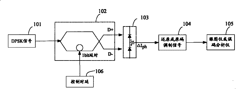
[0004] In principle, the optical fiber decoder is related to factors such as the transmission rate of the modulated signal, the center wavelength of the modulated optical signal, and the working environment temperature. How to adapt the delay time of the optical fiber decoder according to changes in these factors and apply this technology to The terminal problem of miniaturized transmission products has not been effectively solved
However, a balanced differential optical receiver is expensive, and this patented technology cannot be realized without a balanced differential optical receiver

Method used


Image

  • DPSK light modulation signal receiving device and method thereof
  • DPSK light modulation signal receiving device and method thereof
  • DPSK light modulation signal receiving device and method thereof

Examples


Embodiment Construction

[0032] The embodiment of the present invention provides an adjustment mechanism using feedback control, which can automatically adjust the 1-bit (bit) delay of the optical fiber decoder according to changes in the rate of the received DPSK optical modulation signal or operating temperature, thereby obtaining Optimized decoded output signal. This mechanism is especially suitable for high-speed optical transmission systems (such as 10Gb / s and 40Gb / s optical transmission systems) including dense wavelength division multiplexing (DWDM) optical transmission system terminals. Embodiments of the present invention will be described in detail below.

[0033] Device embodiment

[0034] In this embodiment, a modulated signal receiving device is provided.

[0035] Such as Figure 5As shown, the modulation signal receiving device according to the embodiment of the present invention includes: an optical fiber decoder 502, which is used to demodulate the DPSK optical modulation signal, an...


PUM


Abstract

A DPSK optical modulation signal receiving device comprises a fiber decoder to demodulate DPSK optical modulation signals and output demodulated complementary optical signals, a photoelectric detector to converter the complementary optical signal demodulated by the fiber decoder into electric signals, a limiting amplifier to receive the electric signal output by the photoelectric detector and amplify the electric signal, a peak value detector to detect peak value of the amplified electric signal, a time delay control module connected between the fiber decoder and the peak value detector to control time delay of the fiber decoder while the peak value detector fails to find out peak value of the electric signal amplified by the limiting amplifier and a power combiner to combine power of theamplified electric signal output by the limiting amplifier. The present invention can reduce cost and power consumption of optical transmission system terminals, lessen terminal size and realize self-adapting demodulation to DPSK optical modulation signals under conditions of failing to acquire a balanced differential receiving set.

Description

technical field [0001] The present invention relates to the field of optical network communication, and in particular, relates to a DPSK optical modulation signal receiving device and method. Background technique [0002] In recent years, DPSK optical modulation technology has attracted people's attention. The main reason is that this modulation technology can improve the optical receiving sensitivity and optical signal of the transmission system by precoding the baseband modulation signal at the transmitting end and performing differential balanced reception at the receiving end. Tolerant to noise ratio and strong anti-nonlinear ability, it has become the main optical modulation technology for large-capacity, long-distance, and long-span optical transmission systems. [0003] From a technical point of view, the generation of DPSK optical modulation signals is relatively mature, and many related technologies have been proposed. However, there are very few technologies relat...

Claims


Application Information

Patent Timeline
Patent Type & Authority Patents(China)
IPC IPC(8): H04B10/158H04L27/22H04B10/66
Inventor 张立昆许昌武周伟勤
Owner NANJING ZHONGXING XIN SOFTWARE CO LTD
Learn More