Capacitance energy accumulation type fusing soldering welder

A capacitor energy storage type, fusion welding technology, applied in systems, electrical components, nail tools, etc. for storing electrical energy, can solve the problems of easily damaged body, vulnerable transformers, endangering personal safety, etc., and achieve the effect of solving easily damaged

Inactive Publication Date: 2010-07-14
大连威嘉船舶配件有限公司
View PDF0 Cites 0 Cited by
  • Summary
  • Abstract
  • Description
  • Claims
  • Application Information

AI Technical Summary

Problems solved by technology

[0006] Aiming at the above problems, the utility model provides a control circuit of a capacitive energy storage fusion welding machine / fusion welding machine with sequential pulse control and overvoltage protection function, so as to solve the problems of strong and weak currents in such fusion welding machines in the prior art. The problem of easy damage to the body caused by the mixed electricity phenomenon, and the problem of the easy damage of the transformer and the easy damage of the transformer insulation, which endanger personal safety and cause production accidents

Method used


Image

  • Capacitance energy accumulation type fusing soldering welder
  • Capacitance energy accumulation type fusing soldering welder
  • Capacitance energy accumulation type fusing soldering welder

Examples


Embodiment Construction

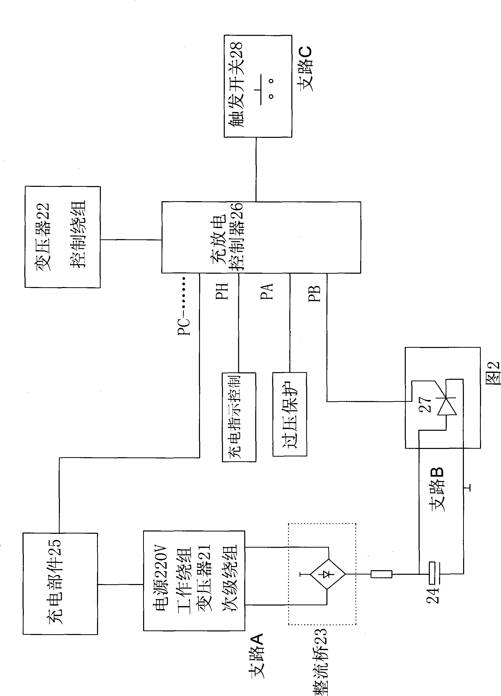
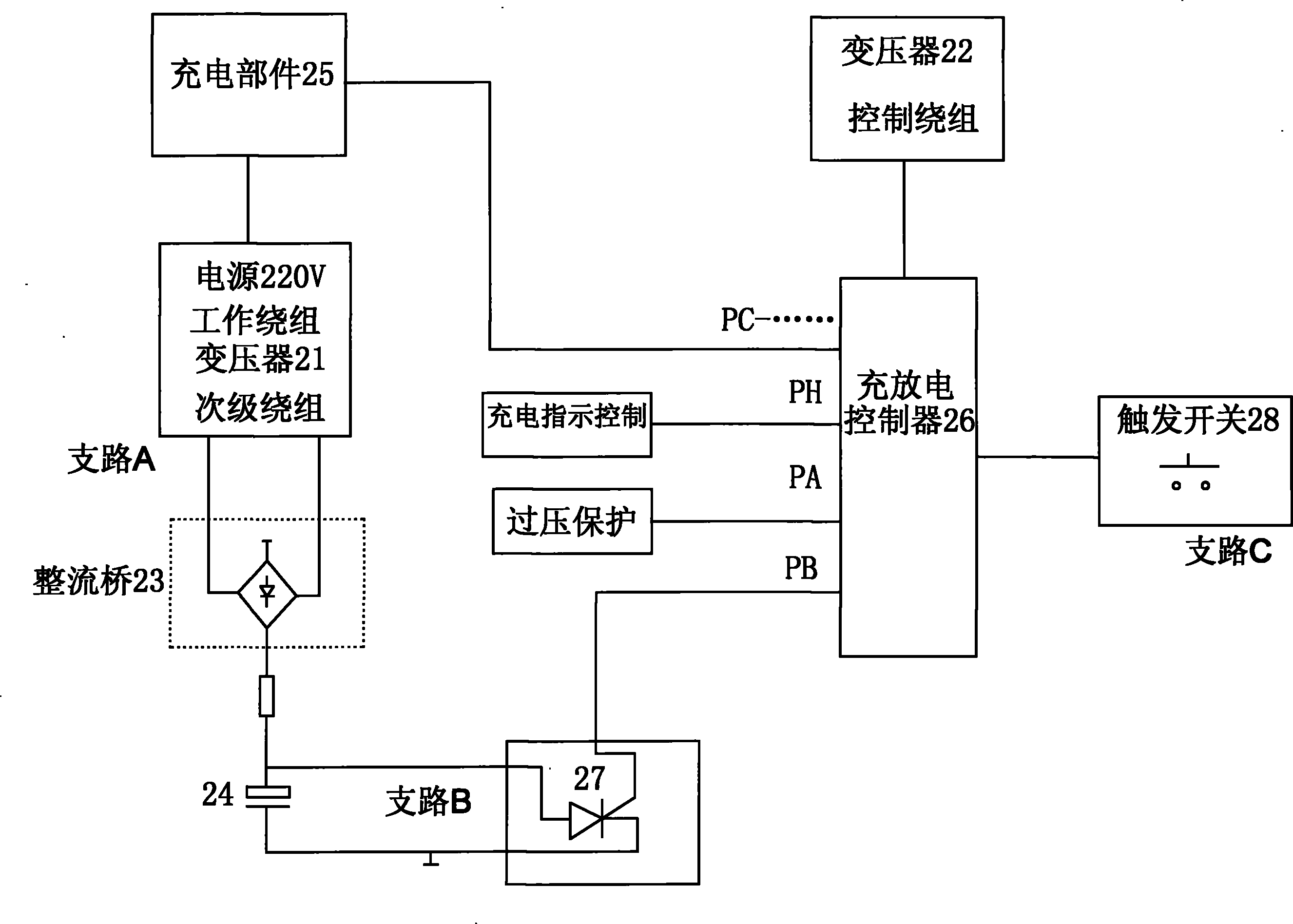
[0016] figure 2 Among them, the charging and discharging controller 26 has multiple output terminals, among which the main terminals such as PA, PB, PC, etc. are connected with each branch and controlled by it in sequence.

[0017] In order to achieve the purpose of being controlled by timing pulses and working reliably: the circuit is specifically designed as follows:

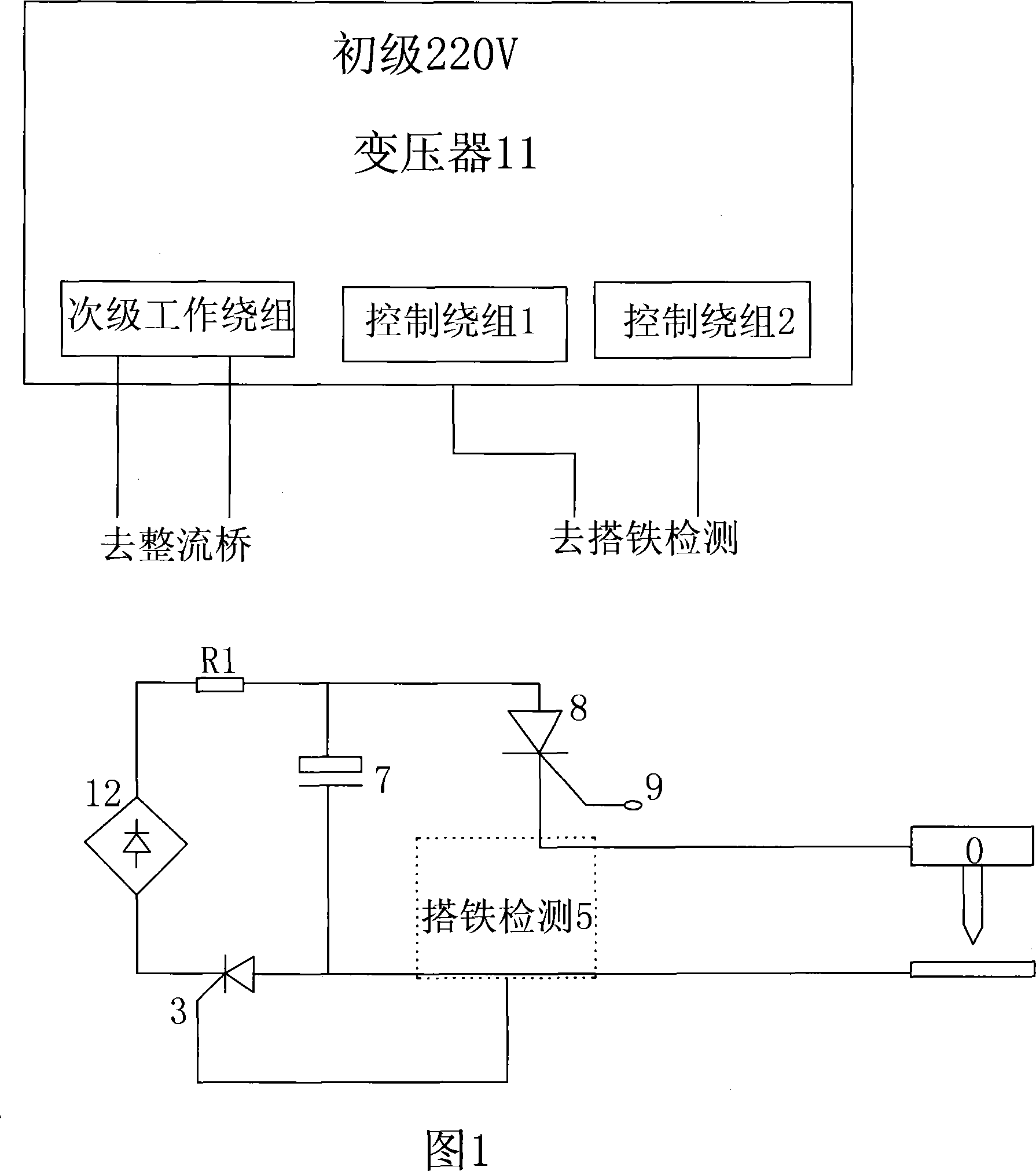
[0018] Among them, the charging component 25, the transformer 21, the rectifier bridge 23, and the energy storage capacitor 24 form the charging branch A; the discharge thyristor 27 and the energy storage capacitor 24 form the discharging branch B, and the trigger switch 28 cooperates with the charge and discharge controller 26 to form a control circuit. Branch C.

[0019] 1. Transformer selection: the working winding and the control winding group of the present invention are divided into two transformers 21 and 22. Because the circuit efficiency is high, the respective powers are all small, and the control ...


PUM


Abstract

A capacitor energy storage nailing machine is disclosed. The charge branch of the nailing machine includes a charge part (25), a transformer (21), a rectifier bridge (23) and an energy storage capacitor (24), which are linked in tandem. A discharge branch includes the energy storage capacitor and a discharge thyristor (27). The charge and discharge branches are connected with a charge / discharge controller (26), which is connected with a trigger switch. The braches of the present capacitor energy storage nailing machine such as charge, discharge, triggering, over voltage protection and charge indication, etc. are respectively controlled by a plurality of output terminals of the charge / discharge controller which are output and scanned by a sequence pulse subterminal which is independently triggered by the trigger switch, thereby separating the strong and weak electricity thoroughly and completely. The present nailing machine can perfectly protect the circuit, can avoid the serious consequences caused by the simultaneous charging and discharging because of a disturbance, can solve the disadvantages that valuable circuit elements of the prior product such as the transformer, the charge thyristor, the relay and the circuit board are easily damaged, and can eliminate hidden dangers caused by the bad insulation of a conductor.

Description

technical field [0001] The utility model relates to a capacitor energy storage type welding machine (nailing machine), in particular to a control circuit for controlling the capacitor energy storage type fusion welding machine. Background technique [0002] At present, the shipbuilding fusion welding machines that have been put into use such as figure 1 shown. Wherein, the control circuit of this type of capacitive energy storage type fusion welding machine in the prior art is electrically connected with the charging thyristor 3, the rectifier bridge 2, the transformer 1, the energy storage capacitor 7, and the discharging thyristor 8 in sequence by the grounding detection 5 constitute. The fusion welding machine relies on the grounding detection 5 to detect whether the gun head 0 is lifted or dropped, so as to control the charging and discharging, that is, it will be charged when it is lifted, and it will be released when it is dropped, and it is directly manually trigger...

Claims


Application Information

Patent Timeline
Patent Type & Authority Patents(China)
IPC IPC(8): B27F7/00H02J15/00
Inventor 李洪建邵金波
Owner 大连威嘉船舶配件有限公司
Why Eureka
Try Eureka