


Quick Research
Generate reliable direction feasibility study reports for your R&D in just a few steps.

Technical Q&A
Discover and master advanced knowledge NOW. Basics, ideas, possibilities, all at once.

Find Solutions
As an expert in R&D theories, this can generate solutions to your technical problems instantly.

Evaluate Feasibility
Analyze your overall solution with one click, know your potential R&D risks in advance.

Monitor Landscape
Get weekly tech updates, stay abreast of the latest tech innovations and key insights.
Ultrasonic diagnostic device, ultrasonic diagnostic device main body, and ultrasonic probe
A diagnostic device, ultrasonic technology, applied in the direction of ultrasonic diagnosis, ultrasonic/sonic/infrasonic data transmission, ultrasonic/sonic/infrasonic diagnosis, etc., which can solve the problems of cost increase and achieve low-cost effects
- Summary
- Abstract
- Description
- Claims
- Application Information
AI Technical Summary
Problems solved by technology
Method used
Image

Examples
no. 1 Embodiment approach
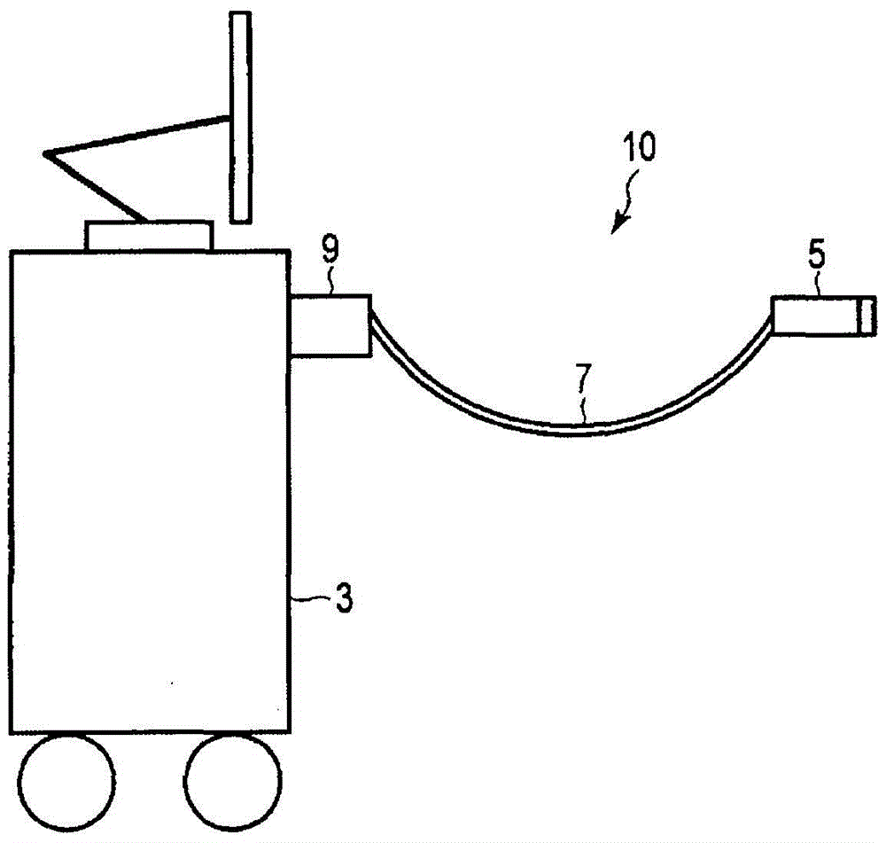
[0017] figure 1 It is a diagram showing a schematic appearance of the ultrasonic diagnostic apparatus according to the first embodiment. like figure 1 As shown, the ultrasonic diagnostic apparatus of the first embodiment includes an ultrasonic probe 1 and an ultrasonic diagnostic apparatus main body 3 . The ultrasonic probe 1 is equipped with a probe head 5 , a probe cable 7 and a probe connector 9 . In the detector head 5, a plurality of devices are built-in. To the base of the probe head 5, a probe cable 7 is connected, and a probe connector 9 is installed at the other end of the probe cable 7. The probe connector 9 is detachably connected to an insertion port (not shown) provided in the ultrasonic diagnostic apparatus main body 3 . In a state where the probe connector 9 is attached to the ultrasonic diagnostic apparatus main body 3 , various electric signals are transmitted and received between the ultrasonic probe 1 and the ultrasonic diagnostic apparatus main body 3 ....
no. 2 Embodiment approach
[0042] In the first embodiment, the device in the ultrasonic probe to which the operating voltage is supplied from the power supply circuit is the HVSW circuit. However, in the present embodiment, the supply destination of the operating voltage is not limited to only the HVSW circuit. The ultrasonic diagnostic apparatus according to the second embodiment incorporates electronic equipment other than the HVSW circuit in the ultrasonic probe. Hereinafter, a second embodiment will be described. In addition, in the following description, the same code|symbol is attached|subjected to the component which has substantially the same function as 1st Embodiment, and description is repeated only when necessary.
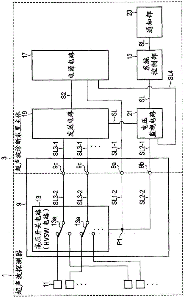
[0043] Figure 5 It is a figure showing the structure of the ultrasonic probe 1 and the ultrasonic diagnostic apparatus main body 3 of 2nd Embodiment. In addition, in Figure 5 In, in order to simplify the description, the receiving circuit system is omitted.
[0044] like ...
PUM
 Abstract
Description
Claims
Application Information
 - R&D Engineer
- R&D Manager
- IP Professional
- Industry Leading Data Capabilities
- Powerful AI technology
- Patent DNA Extraction
Browse by: Latest US Patents, China's latest patents, Technical Efficacy Thesaurus, Application Domain, Technology Topic, Popular Technical Reports.
© 2024 PatSnap. All rights reserved.Legal|Privacy policy|Modern Slavery Act Transparency Statement|Sitemap|About US| Contact US: help@patsnap.com