Optical disk reproducing device

A technology for reproducing devices and optical discs, applied in the directions of optical recording/reproducing/erasing methods, optical record carriers, optical reproduction systems, etc.

Inactive Publication Date: 2008-03-05
PANASONIC CORP
View PDF2 Cites 2 Cited by
  • Summary
  • Abstract
  • Description
  • Claims
  • Application Information

AI Technical Summary

Problems solved by technology

[0039] The present invention is proposed to solve the above-mentioned problems, and it provides an optical disc playback device capable of stably reading NBCA and BCA even when the tracking servo control in the unrecorded portion of the RF signal cannot be performed.

Method used


Image

  • Optical disk reproducing device
  • Optical disk reproducing device
  • Optical disk reproducing device

Examples


Embodiment approach 1

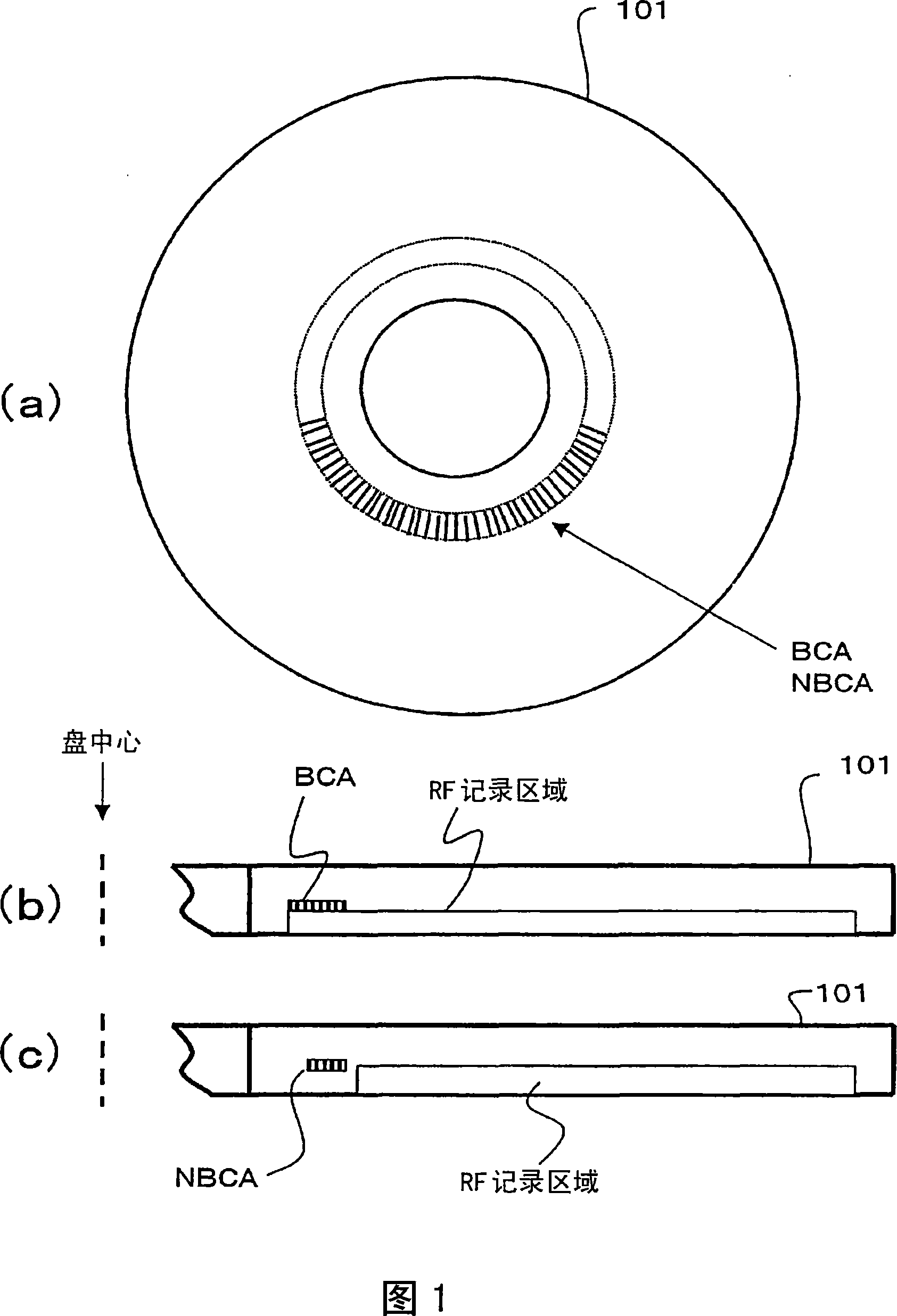
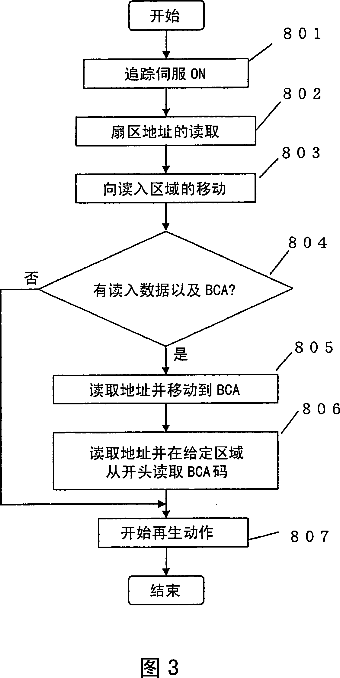
[0071] Referring to FIG. 4, a first embodiment of an optical disk reproducing apparatus according to the present invention will be described. The optical disc playback device of this embodiment can read data (disc-specific information, etc.) from the NBCA of the optical disc 101 having the NBCA.

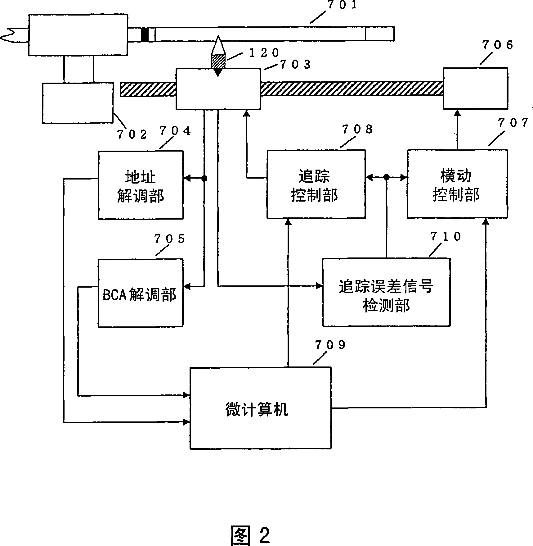
[0072] This optical disc playback device has: a spindle motor 102 for rotating the optical disc 101, an optical pickup 103 for irradiating the optical disc 101 with a light beam and generating an electrical signal based on the reflected light, and a base for moving the optical pickup 103 in the radial direction of the optical disc 101. The conveying mechanism 106, and the control unit 200 that controls the above-mentioned components.

[0073] The control part 200 has: the NBCA inside and outside judging part 104 that judges whether the beam irradiation position is located in the NBCA area according to the electric signal generated by the optical pickup 103, the NBCA demodulation part...

Embodiment approach 2

[0109] Next, a second embodiment of the optical disk reproducing apparatus of the present invention will be described.

[0110] Referring first to FIG. 11 . FIG. 11 is a block diagram of an optical disc playback device in this embodiment.

[0111] The difference between the configuration of the optical disc playback device in this embodiment and the configuration of the optical disc playback device in Embodiment 1 is that the optical disc playback device in this embodiment replaces the NBCA internal / external determination unit 104 and the NBCA demodulation unit 105, and has a BCA internal / external determination unit. Section 404 and BCA demodulation section 405. Other components are common to both embodiments, and description of the common parts will be omitted here.

[0112] The BCA area determination unit 404 determines whether or not the beam irradiation position is located within the BCA area based on the reproduced signal from the optical pickup 103 . The BCA demodulat...


PUM


Abstract

An optical disk reproducing device, capable of reading information from the NBCA of an optical disk (101) provided with the NBCA, comprising an optical pickup (103) having an object lens (120) condensing a light beam onto the optical disk (101), a lens actuator (170) controlling the position of the object lens (120), and a light detector generating an electrical signal from at least part of a light beam reflected off the optical disk (101), a feeding mechanism (106) moving the optical pickup (103) in the radial direction of the optical pickup (103), and an NBCA inside-outside judging unit (104) for judging whether or not the irradiation position of a light beam on the optical disk (101) is positioned inside the NBCA based on the electrical signal. Step A for moving the optical pickup (103) from a first pickup position to a second pickup position closer to the disk center by means of the feeding mechanism (106) when information is read from the NBCA, step B for locating the object lens (120) sequentially to a plurality of different positions inside the optical pickup (103) on the second pickup position, and step C for judging whether or not the irradiation position of a light beam condensed by the object lens (120) on the optical disk (101) is positioned inside the NBCA by means of NBCA inside-outside judging unit (104) are performed.

Description

technical field [0001] The present invention relates to an optical disk reproducing device and a driving method thereof. Background technique [0002] The data recorded on the optical disc is reproduced by irradiating a rotating optical disc with a relatively weak light beam of a certain amount of light and detecting the reflected light modulated by the optical disc. [0003] In a reproduction-only optical disc, information based on information pits is recorded in a spiral shape in advance at the manufacturing stage of the optical disc. In contrast, in rewritable optical discs, optically recordable / A recording material film for reproducing data. When recording data on a rewritable optical disc, the optical disc is irradiated with a light beam modulated according to the data to be recorded, and the characteristics of the recording material film are locally changed in this way to write data. [0004] In addition, the depth of the information pit, the depth of the track, an...

Claims


Application Information

Patent Timeline
Patent Type & Authority Applications(China)
IPC IPC(8): G11B7/085G11B7/005G11B7/007G11B7/24
CPCG11B7/0053G11B7/08582G11B7/08505
Inventor 佐藤美千则
Owner PANASONIC CORP
Why Eureka
Try Eureka