Solar collector

A technology for solar collectors and solar energy absorption, applied in solar collectors, solar collector controllers, mobile/directional solar collectors, etc., can solve problems such as collector efficiency decline

Inactive Publication Date: 2008-03-05
D·J·琼斯 +1
View PDF0 Cites 5 Cited by
  • Summary
  • Abstract
  • Description
  • Claims
  • Application Information

AI Technical Summary

Problems solved by technology

Due to this effect, the efficiency of conventional collectors drops rapidly as the temperature of the heated fluid increases until eventually the loss of long-wave radiation from the collector surface equals the absorption of short-wave radiation by the collector, and no further heating

Method used


Image

  • Solar collector
  • Solar collector
  • Solar collector

Examples


Embodiment Construction

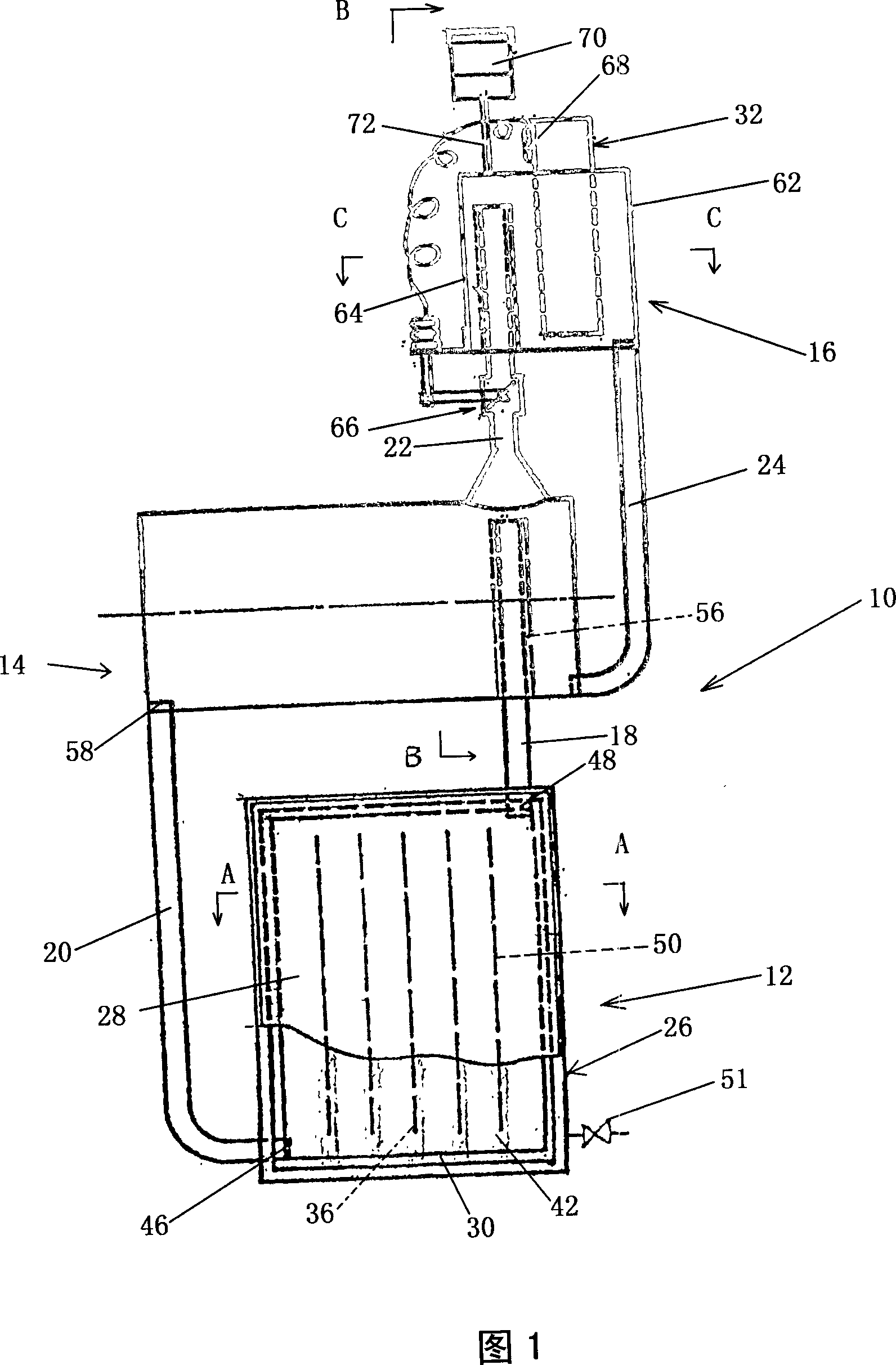
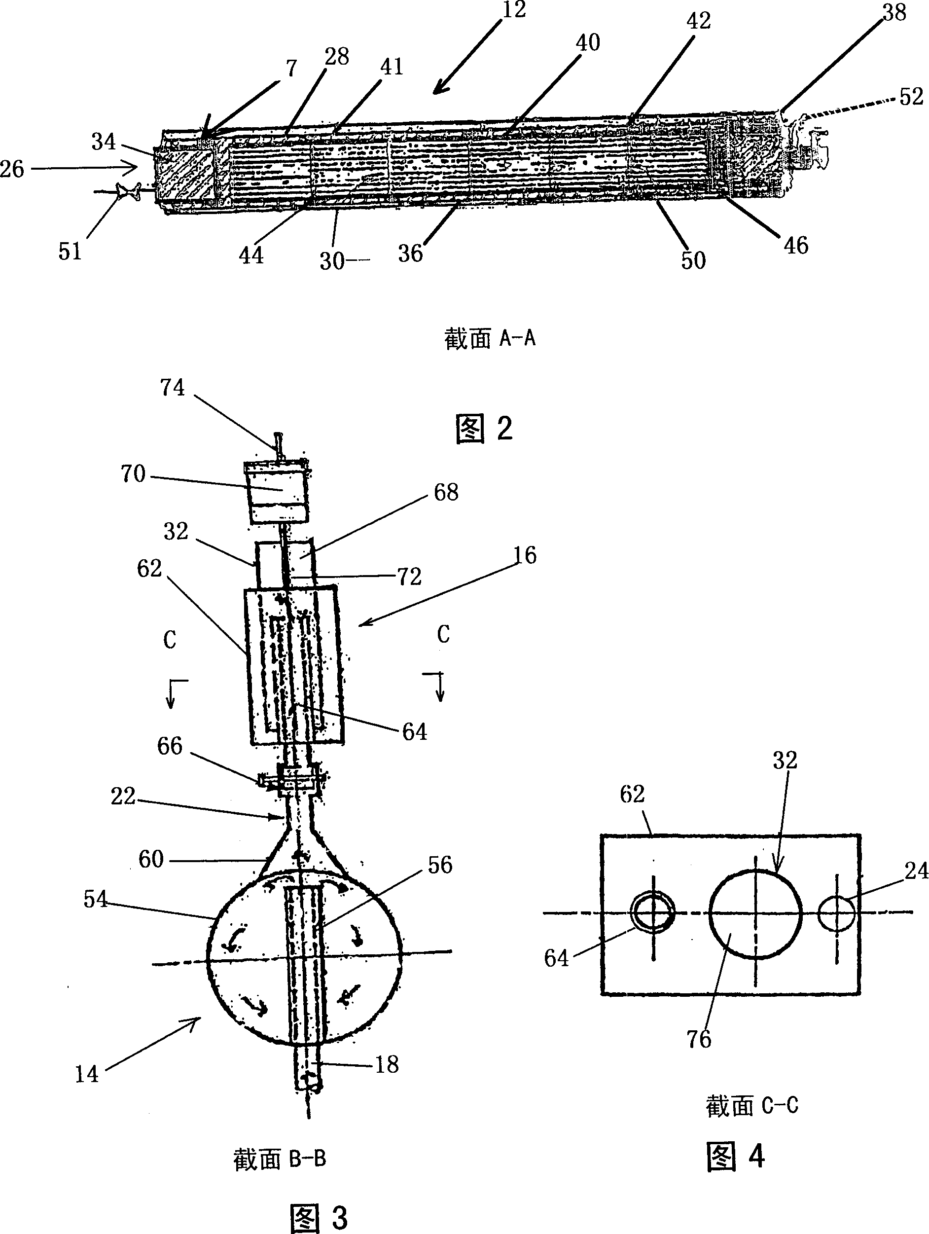
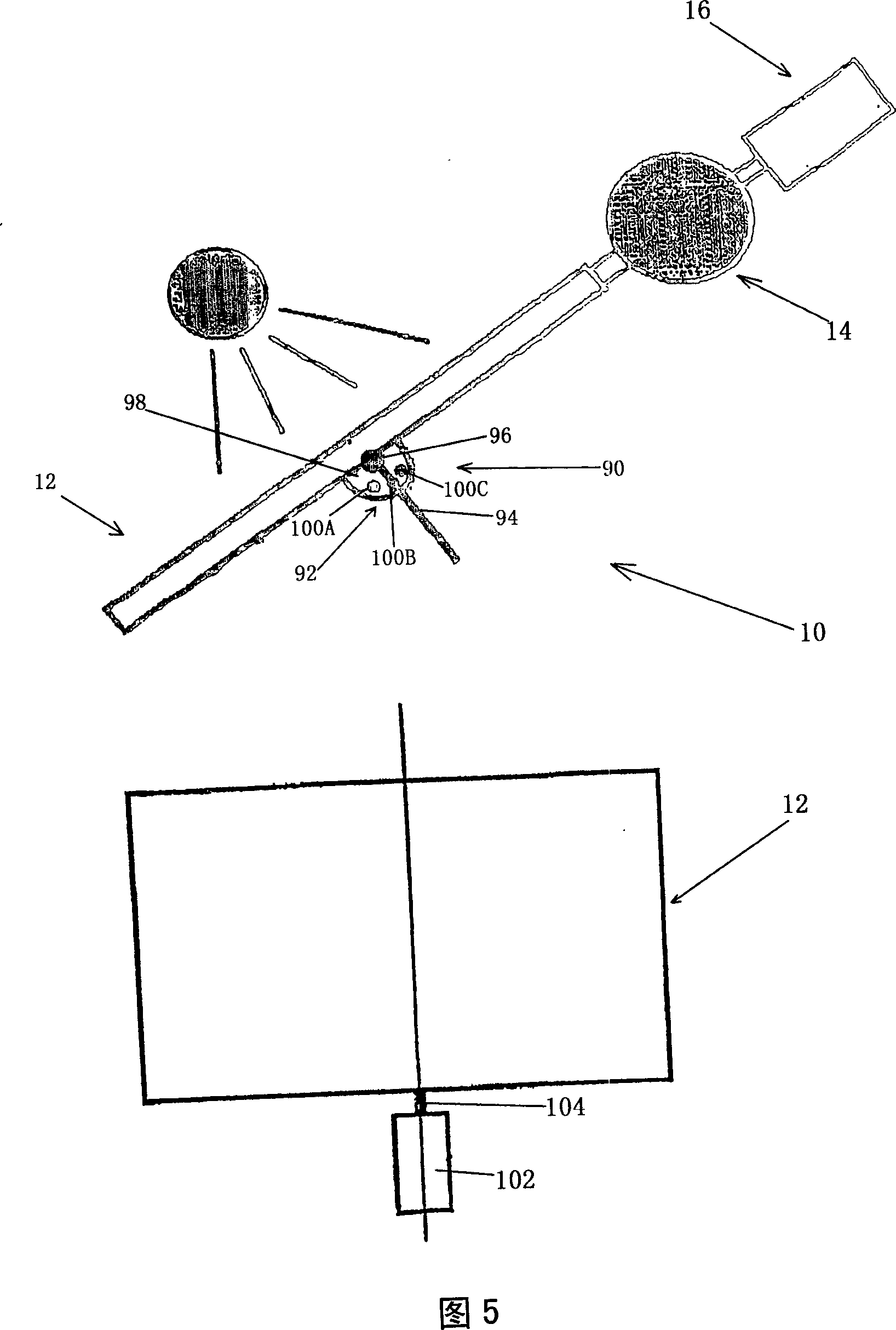
[0037] As shown in FIG. 1 , a solar heat exchanger, generally indicated at 10 , includes a solar collector 12 , a heat accumulator 14 and a heat exchanger 16 . Solar collector 12 is operatively coupled to heat storage 14 through supply conduit 18 and recirculation conduit 20 . In operation, regenerator 14 is coupled with heat exchanger 16 via supply conduit 22 and return conduit 24 in turn.

[0038] The solar collector 12 includes a collector housing 26 having a translucent or transparent surface in the form of a glass window 28 . The solar collector 12 also has a collector cavity 30 which is located inside the collector housing 26 and which is adapted in operation to contain a heat transfer fluid such as glycol or a water / glycol mixture . The water / glycol mixture is heated by the solar collector 12 and is circulated between the solar collector 12 and the thermal storage 14 through the supply pipe 18 and the recirculation pipe 20 respectively due to the thermosiphon effect. ...


PUM


Abstract

The invention is a solar powered heat exchanger (10) comprising a solar collector (12), a heat accumulator (14), and a heat exchanger (16). The solar collector is operatively coupled to the heat accumulator (14) via a supply line (18) and a recirculation line (20). The heat accumulator (14) is in turn operatively coupled to the heat exchanger (16) via a feed line (22) and a return line (24).

Description

technical field [0001] The present invention relates broadly to a solar collector and to a solar heat exchanger. The invention also relates to a solar tracking device and a combined solar collector / tracking device. Background technique [0002] A solar water heating system of conventional construction includes a solar collector connected to a storage cylinder containing stored water. Solar collectors are manufactured by means of multiple heat-absorbing tubes or tubes arranged in parallel or helically. In one form, the tubes are formed on a black heat absorbing base that can be placed on a roof to capture sunlight. In another form, the tubes are enclosed in an enclosure with glass panes exposed to sunlight, improving heating efficiency due to the effects of the greenhouse effect. This system can provide direct heating, where the stored water itself is circulated through solar collectors. Alternatively, indirect heating may be provided where, for example, the glycol mixtur...

Claims


Application Information

Patent Timeline
Patent Type & Authority Applications(China)
IPC IPC(8): F24J2/05F24J2/38F24S50/20F24S10/40
CPCF24J2/44F24J2/5424F24J2/05F24J2/38Y02E10/44F24J2/345F24J2/523Y02E10/47F24S30/455F24S60/30F24S50/20F24S25/10F24S90/10F24S10/40
Inventor D·J·琼斯G·A·柯林斯
Owner D·J·琼斯
Why Eureka
Try Eureka