Analysis method for electrical characteristic of parallel connection and parallel-serial connected piezoelectric voltage transformer

A technology of piezoelectric transformers and electrical characteristics, applied in piezoelectric/electrostrictive/magnetostrictive devices, electrical components, measuring electrical variables, etc. The complex manufacturing technology of piezoelectric transformers

Inactive Publication Date: 2008-03-05
DALIAN UNIV OF TECH
View PDF0 Cites 5 Cited by
  • Summary
  • Abstract
  • Description
  • Claims
  • Application Information

AI Technical Summary

Problems solved by technology

However, the first two methods have the following disadvantages: First, the manufacturing technology of multilayer piezoelectric transformers is very complicated, the consistency of mass production is poor, and the cost is high; the multilayer piezoelectric transformers of various manufacturers are very different and cannot be interchanged, and the structure of the control loop , the working principle is not the same, which hinder the further popularization and application of multilayer piezoelectric transformers
Second, improve the structure and vibration mode of the piezoelectric transformer. For example, in 2005, the 26th Research Institute of China Electronics Technology G

Method used


Image

  • Analysis method for electrical characteristic of parallel connection and parallel-serial connected piezoelectric voltage transformer
  • Analysis method for electrical characteristic of parallel connection and parallel-serial connected piezoelectric voltage transformer
  • Analysis method for electrical characteristic of parallel connection and parallel-serial connected piezoelectric voltage transformer

Examples


Embodiment 1

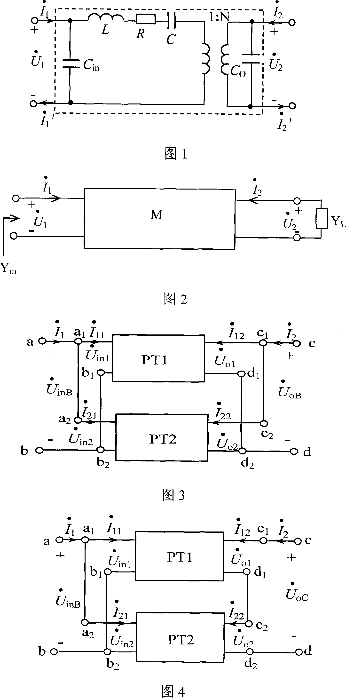
[0025] Embodiment 1: Two piezoelectric transformers with the same parameters are connected in parallel, and the input terminal a of PT1 1 With the input terminal a of PT2 2 Connected, as input terminal a after parallel connection, input terminal b of PT1 1 With the input terminal b of PT2 2 Connected, as the input terminal b after parallel connection; the output terminal c of PT1 1 With the output terminal c of PT2 2 Connected, as the output terminal c after parallel connection, the output terminal d of PTl 1 With the output terminal d of PT2 2 Connected, as the output terminal d after parallel connection. The limiting condition for parallel-parallel connection is: the input voltage and output voltage are respectively forced to be the same, namely U · in 1 = U · in 2 =...

Embodiment 2

[0030] Embodiment 2: Two piezoelectric transformers with the same parameters are used in parallel-series connection, and the input terminal a of PT1 1 With the input terminal a of PT2 2 Connected, as input terminal a after parallel-parallel connection, input terminal b of PTl 1 With the input terminal b of PT2 2 Connected, as the input terminal b after parallel-parallel connection; the output terminal d of PTl 1 With the output terminal c of PT2 2 connected, terminal c 1 As output terminals c, d after parallel-series connection 2 As the output terminal d after parallel-series connection. The limiting condition for parallel-series connection is that the input voltage and output current are respectively forced to be the same, namely U · in 1 = U · in 2 = ...


PUM


Abstract

The method comprises: using the traditional lumped parameter equivalent-circuit model of the piezoelectric transformer, and using the admittance matrix Y to express the voltage gain, output power and correlated relation between the transmission efficiency specification and the piezoelectric transformer connection numbers (n) of the piezoelectric transformer.

Description

technical field [0001] The invention belongs to the field of electronic transformers, and relates to the connection of piezoelectric transformers and an analysis method for electrical characteristics, in particular to an analysis method for the electrical characteristics of piezoelectric transformers using parallel-parallel and parallel-series connections. Background technique [0002] In recent years, piezoelectric transformer (Piezoelectric transformer, referred to as PT), as a new type of electronic device, has become one of the research hotspots in the field of materials and information. , high conversion efficiency, small temperature rise, no electromagnetic interference and other outstanding advantages, it has broad application prospects in the fields of notebook computers, LCD displays and other backlight power supplies, household appliances and instruments. However, with the rapid development of the information industry, the LCD screen is getting bigger and bigger, a...

Claims


Application Information

Patent Timeline
IPC IPC(8): G01R31/00G01R19/00G01R21/00H01L41/107
Inventor 白凤仙董维杰肖磊
Owner DALIAN UNIV OF TECH
Why Eureka
Try Eureka