Pick-blowing nozzle for fluid jet loom

A technology of fluid jetting and looms, applied in looms, textiles, textiles and papermaking, etc., can solve problems such as loss of function, weft yarn damage, complex structure, etc., and achieve the effect of simple structure

Inactive Publication Date: 2011-01-12
TSUDAKOMA KOGYO KK
View PDF11 Cites 0 Cited by
  • Summary
  • Abstract
  • Description
  • Claims
  • Application Information

AI Technical Summary

Problems solved by technology

However, the problem with this technology is that the structure becomes complicated due to the active drive mechanism
However, there is a problem with this technique that since the linear member is always in contact with the weft yarn, the weft insertion becomes unstable, or the weft yarn is damaged, etc.
However, there is a problem that the structure becomes complicated due to the need for a mechanism to control the air injection. In addition, if flying flowers and the like stay in the air, the function will be lost, so it must be removed regularly.

Method used


Image

  • Pick-blowing nozzle for fluid jet loom
  • Pick-blowing nozzle for fluid jet loom
  • Pick-blowing nozzle for fluid jet loom

Examples


Embodiment Construction

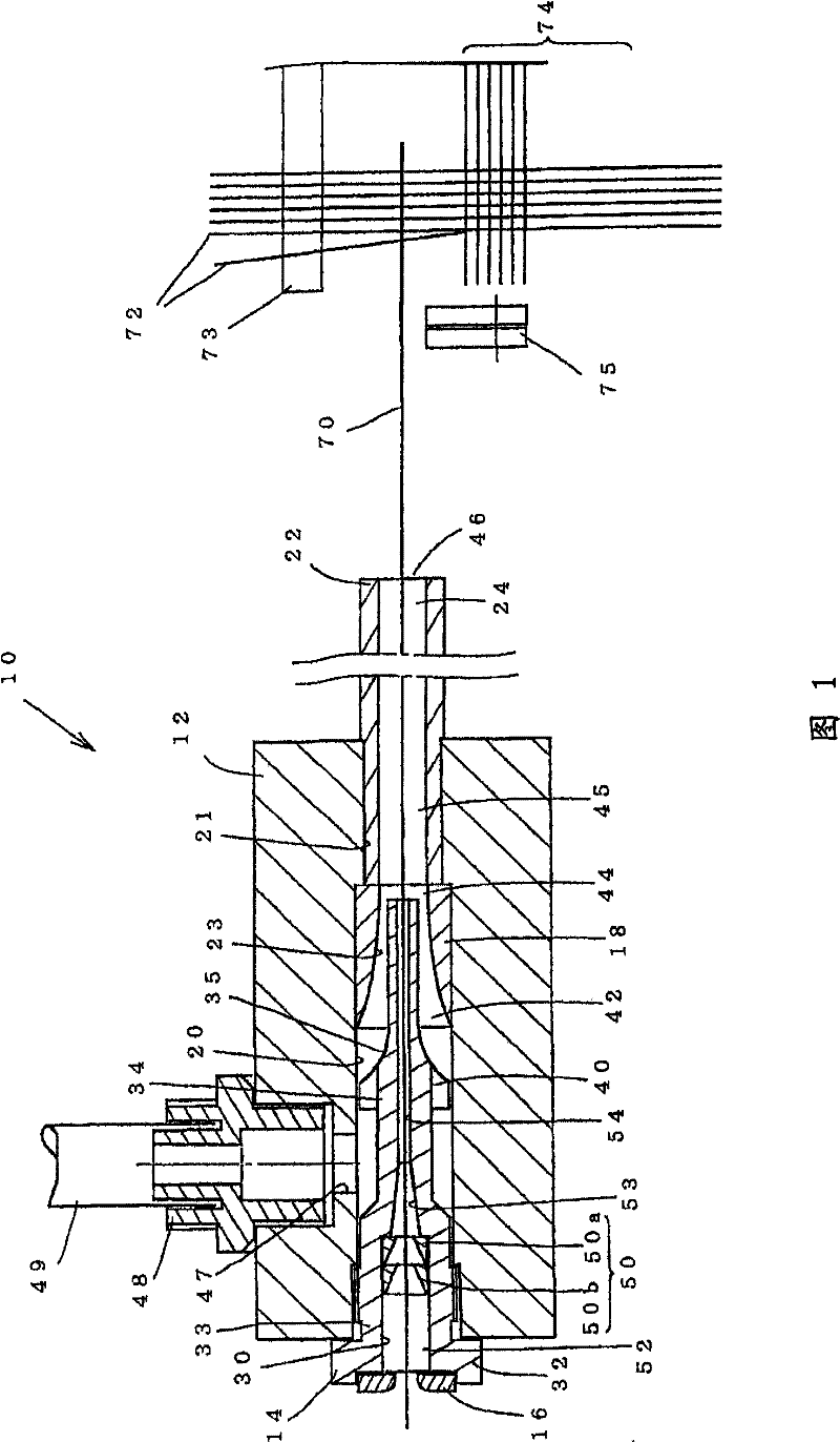
[0028] As the weft insertion nozzle 10 that can specifically implement the present invention, the main nozzle used by the air-jet loom is taken as an example, and the following uses Figure 1 ~ Figure 2 Be explained. refer to Figure 1 ~ Figure 2 The weft insertion nozzle 10 mainly includes: for example, its outer diameter forms a cylindrical shape, a nozzle body 12 having a through insertion hole 20 in its center; Yarn guide 14 in 20.

[0029] The nozzle main body 12 coaxially has a first insertion hole 20 opened on one end (rear end) side and a second insertion hole 21 communicated with the first insertion hole 20 and opened on the other end (front end) side. Both the first insertion hole 20 and the second insertion hole 21 have a circular cross-sectional shape, and the diameter of the former is larger than that of the latter.

[0030] A throttling member 18 having a through hole is coaxially inserted into the first insertion hole 20 from one end (rear end) side, and a cy...


PUM


Abstract

The invention provides a wefting nozzle for preventing weft yarn with strong retractility separating from the nozzle. A guiding piece (50) is arranged a holding portion (52) of a yarn carrier (14) of the wefting nozzle (10), which has a conical surface (57) and a downstream side opposite surface (58), wherein, the conical surface (57) is reduced in the radial direction gradually from the upstreamside to the downstream side, the inside diameters (d1, d2) of the downstream side end portion (61) are the smallest inside diameters of the guiding hole (55) and smaller than that of the upstream side end portion (66) of the guiding portions (53, 54), the downstream side opposite surface (58) is continuous from a downstream side inner circumferential end (61) of the conical surface (57) to a downstream side cirumferential end (62) of the guiding piece.

Description

technical field [0001] The present invention relates to a weft insertion nozzle of a fluid jet loom, and more specifically, relates to a technique for preventing a weft yarn that is highly stretchable from being separated from the nozzle during weaving. Background technique [0002] Fluid jet looms use weft insertion nozzles that inject weft yarns into warp openings. The weft yarn is passed through the weft injection nozzle in advance, and when the warp yarn opening is formed and the specified weft insertion start timing is reached, the weft yarn is injected with the jet fluid ejected from the weft injection nozzle for weft insertion. And, when the weft yarn reaches the vicinity of the nose cloth on the opposite side of the weft insertion, the injection of the jet fluid is ended, and then the warp yarn becomes a closed state, and the weft yarn is driven into the cloth fell by the advancing reed. After that, the weft yarn connected to the weft insertion nozzle and the fabric...

Claims


Application Information

Patent Timeline
Patent Type & Authority Patents(China)
IPC IPC(8): D03D47/30D03D47/28
CPCD03D47/3013
Inventor 伴场秀树
Owner TSUDAKOMA KOGYO KK
Why Eureka
Try Eureka