Control device, device control system, device control program, computer-readable recording medium containing the device control program, and setting check data creation method

A control device and data technology, which is applied in telemetry/remote control selection device, data exchange through path configuration, selection device, etc. It can solve the problems of time-consuming cost, not all function information may be disclosed, and function information cannot be obtained from the server. , to achieve the effect of seeking efficiency and suppressing useless communication

Inactive Publication Date: 2008-02-27
PANASONIC CORP
View PDF0 Cites 11 Cited by
  • Summary
  • Abstract
  • Description
  • Claims
  • Application Information

AI Technical Summary

Problems solved by technology

[0003] However, in general, because there are many kinds of household electrical appliances mixed together in the family, the manufacturers or product numbers are not the same. Manage the function information of all model product numbers, but the function information of all model product numbers of each manufacturer may not be disclosed.
Moreover, since the function information of the latest model may not be registered on the server soon, therefore, in this case, there will be a problem that the function information cannot be obtained from the server, and the home appliance cannot be completely controlled.
In addition, there will also be a problem that it will take a lot of time and money to manage these functional information whether it is centralized management using one server or decentralized management using multiple servers
Moreover, it is also considered that a control device that stores functional information from the beginning needs to install a large-capacity memory in order to store the functional information of each manufacturer or all model product numbers; device, it cannot be controlled

Method used


Image

  • Control device, device control system, device control program, computer-readable recording medium containing the device control program, and setting check data creation method
  • Control device, device control system, device control program, computer-readable recording medium containing the device control program, and setting check data creation method
  • Control device, device control system, device control program, computer-readable recording medium containing the device control program, and setting check data creation method

Examples


Embodiment 1

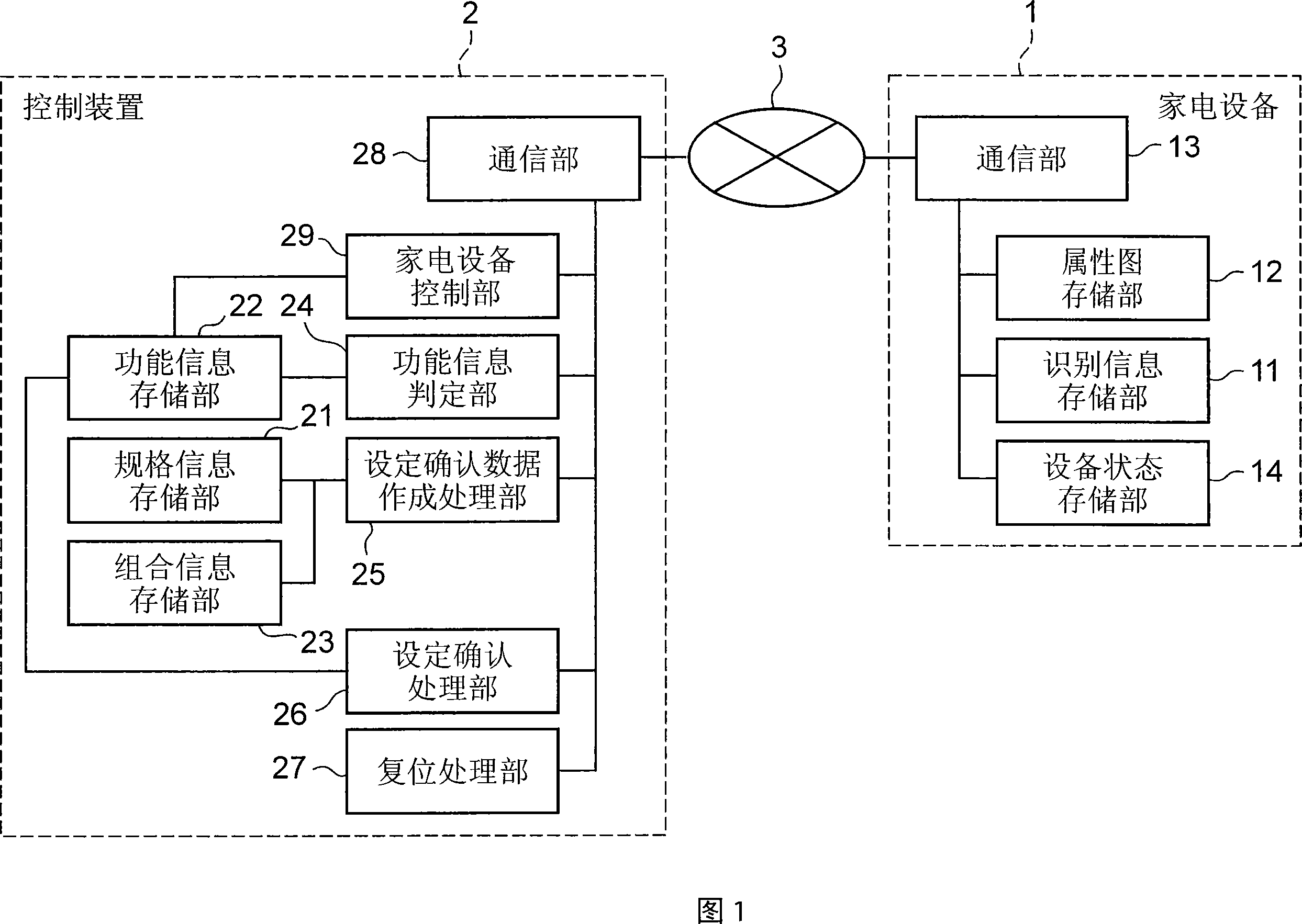
[0068] FIG. 1 is a schematic diagram of the structure of a household appliance control system according to Embodiment 1 of the present invention. In FIG. 1 , the household appliance control system of this embodiment includes a household appliance 1 , a control device 2 and a network 3 . Network 3 is a home network, which can be wired or wireless.

[0069]The household electrical appliance 1 includes an identification information storage unit 11 for storing identification information for identifying the household electrical appliance 1, a property map storage unit 12 for storing a property map, a communication unit 13 for transmitting and receiving data with the control device through the network 3, and a storage unit for storing the household electrical appliance. The device state storage unit 14 of the current state (setting value of the setting item) of 1.

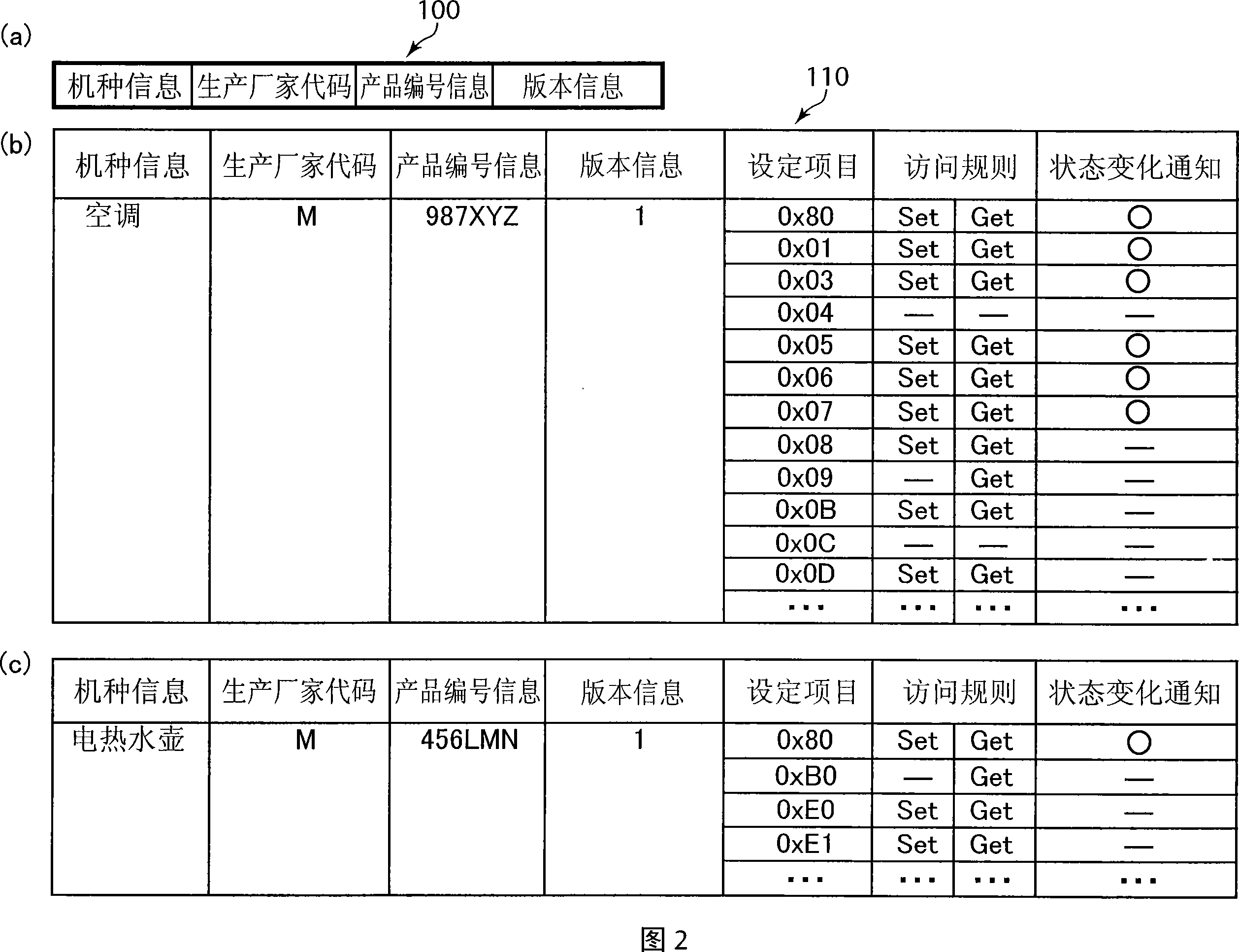
[0070] The identification information includes at least model information indicating the type of the home appliance 1...

Embodiment 2

[0173] Fig. 23 is a schematic diagram of the structure of the household appliance control system according to Embodiment 2 of the present invention. In FIG. 23, the same reference numerals are used for the same components as those in FIG. 1, and description thereof will be omitted here. In this embodiment, in addition to the structure of the household appliance control system in FIG. 1 , it also includes a server 4 and a network 5 .

[0174] The network 5 is a network outside the home, and the control device 2 and the server 4 are connected to each other via the network 5 so as to be communicable. The server 4 provides the control device 2 with function information matching the identification information received from the control device 2 based on the request from the control device 2 .

[0175] The server 4 includes a function information storage unit 41 , a function information determination unit 42 and a communication unit 43 . The function information storage unit 41 sto...

Embodiment 3

[0187] Fig. 25 is a schematic diagram of the structure of the household appliance control system according to Embodiment 3 of the present invention. In FIG. 25, the same reference numerals are used for the same components as those in FIG. 1, and description thereof will be omitted here. The control device 2 in FIG. 25 further includes a protocol processing unit 30 and a protocol information management unit 31 .

[0188] The protocol information management unit 31 stores protocol information for communication with the household electrical appliance 1 . The protocol information management unit 31 stores a protocol information management table in which protocols that can be handled by the control device 2 are associated with household electrical appliances compatible with the protocols. FIG. 26 is a schematic diagram of an example of a protocol information management table stored in the protocol information management unit 31 .

[0189] The protocol management table shown in FI...


PUM


Abstract

It is possible to automatically acquire function information on electric devices manufactured by different manufactures and having different model numbers. A technical standard information storage unit (21) stores technical standard information defining the function information containing at least a setting item for controlling a home electric appliance (1) together with an identifier. A setting check data creation unit (25) acquires the identifier of the home electric appliance (1) and creates setting check data for checking setting for each of the setting items of the home electric appliance (1) according to the technical standard information matched with the model information and version information contained in the identifier. A setting check unit (26) executes setting of the home electric appliance (1) by using the setting check data and updates the function information according to the setting result. A home electric appliance control unit (29) controls the home electric appliance (1) according to the function information.

Description

technical field [0001] The present invention relates to a method for creating setting confirmation data sent to electrical equipment when collecting functional information such as setting items and setting values ​​for controlling electrical equipment connected through a network, and using the setting confirmation data to collect electrical equipment. A control device for functional information, a facility control system, a facility control program, and a computer-readable recording medium on which the facility control program is recorded. Background technique [0002] Recently, as the communication infrastructure (communication infrastructure) in the home, in addition to the network that needs high-speed and large-capacity data transmission such as images, there are various white goods that can be used in the home (for example, air conditioners, refrigerators, microwave ovens, Washing machines, etc.) or a network of low-cost equipment systems with relatively slow speed and ...

Claims


Application Information

Patent Timeline
Patent Type & Authority Applications(China)
IPC IPC(8): G06F13/00H04Q9/00
CPCH04L12/2803H04L12/281
Inventor 前田康孝片野寿昭庄田明
Owner PANASONIC CORP
Why Eureka
Try Eureka