
A railway engine AC traction one-phase power supply device based on YN,vd wiring transformer

A technology of in-phase power supply and transformer, which is applied in the direction of conversion equipment for intermediate conversion to DC, conversion equipment for conversion to DC without intermediate conversion, single-network parallel feeding arrangement, etc., which can solve the problems of accuracy and reliability. Serious problems, technology and economy are difficult to achieve the ideal state, restricting the development of both railways and electric power, etc., to achieve economic and safe and reliable operation guarantee, avoid electricity phase separation, and improve the balance of load

Inactive Publication Date: 2008-02-20
SOUTHWEST JIAOTONG UNIV
View PDF0 Cites 9 Cited by
  • Summary
  • Abstract
  • Description
  • Claims
  • Application Information

AI Technical Summary

Problems solved by technology

Although there is an automatic over-phase separation device, due to its high voltage and frequent switching actions, there are serious problems in its accuracy and reliability, and it cannot completely solve the adverse effects of electric separation on locomotive operation.
[0007] (2) High-speed and heavy-duty transportation all require large-capacity power supply. In order to meet the national standard for the power system to restrict the power quality of electrified railways, the reactive power compensation technology used in the original single-phase power supply mode has been changed. unable to adapt
If the adjustable symmetrical compensation technology is adopted in the traction substation, even if the AC-DC-AC power supply (regardless of its reactive power and harmonics) is used on the locomotive, the negative sequence is more prominent because of the larger capacity, technically and economically. Difficult to achieve the ideal state
[0008] (3) The high-speed railway to be built in my country may be a mixed operation mode of high and medium speeds. If there is a mixed use of locomotives with AC-DC-AC power supply and locomotives with AC-DC power supply, except for negative sequence, reactive power and harmonics will still remain Existence, power quality cannot be improved, restricting the development of both railways and electric power

Method used


Image

  • A railway engine AC traction one-phase power supply device based on YN,vd wiring transformer

Examples


Embodiment 1

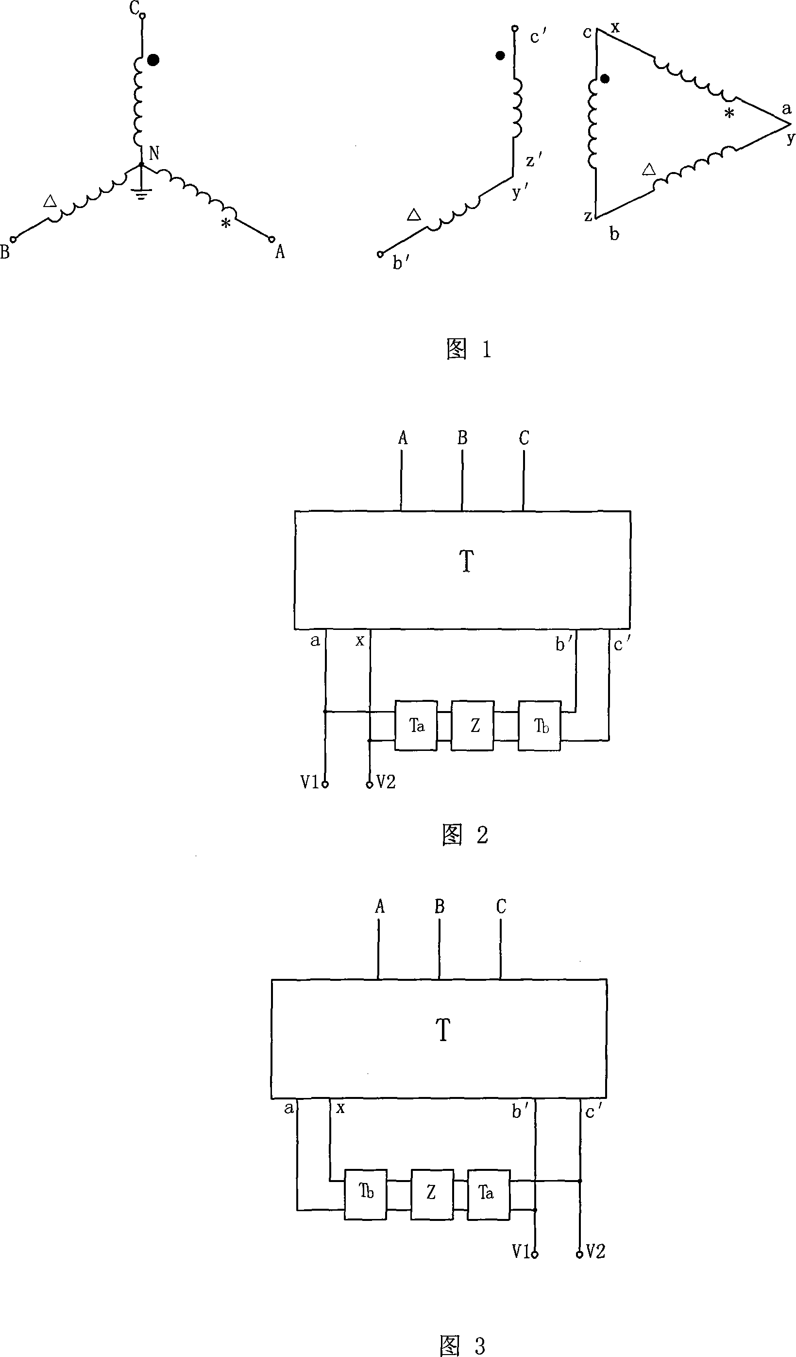
[0030] Fig. 1 shows, a kind of specific structure of the present invention is: a kind of based on YN, in the railway locomotive AC traction in-phase power supply device of vd connection transformer, traction transformer is YN, the three-phase-two-phase balance transformer T of vd connection method, The three primary windings AN, BN, and CN of the YN connection of the transformer T are connected to the high-voltage public power grid, and the two output terminals b', c' of the secondary windings b'y', c'z' of the V connection are used as wires Voltage output terminals b', c'; two ends a, x of a secondary winding ax in the d connection method are used as phase voltage output terminals a, x, and the iron core wound by the winding ax (that is, the iron marked with * in the figure The secondary windings b'y' and c'z' of v-connection are not wound on the core).

[0031] Figure 2 shows that a rectifier inverter Z is connected between the transformer T line voltage output terminals b',...

Embodiment 2

[0036]Figure 3 shows that this example is basically the same as the first example, the only difference is that the line voltage output terminals b' and c' are used as the power supply terminals V1 and V2 of the traction locomotive; thus the phase voltage output terminals a and x of the transformer T pass through A step-down transformer Tb is connected to the input terminal of the rectifier inverter Z, and the output terminal side of the rectifier inverter Z is connected to the line voltage output terminals b' and c' through the step-up transformer Ta.

[0037] The device in this example is applicable when the power supply arm of the common traction power supply device in the adjacent substation is line voltage.

[0038] Obviously, when the device of the present invention is also used in adjacent substations, the power supply end can be either phase voltage output end or line voltage output end, as long as the adjacent substations use the same output end.


PUM


Abstract

The utility model relates to an A.C. co-phase traction supply device of railway locomotive based on YN, vd wiring transformer; wherein, the traction transformer is a three-phase to two-phase balancing transformer (T), the wiring method of which is YN, vd. A rectifying inverter (Z) is connected between two outputs (b', c') of the line voltage of the transformer (T) and two outputs (a, x) of the phase voltage of the transformer (T), and the outputs (b', c') of the line voltage and the outputs (a, x) of the phase voltage are the supply ends (V1, V2) of the traction locomotive. Meanwhile, a control device of the rectifying inverter (Z) is connected with the two supply ends (V1, V2) of the traction locomotive. The utility model has the advantages of achieving the co-phase power supply in the whole line of the railway without dividing phases, being stable voltage in each section of the traction transforming station, ensuring that the locomotives can move at high speed when the locomotives are overloading, getting the power in three-phase from the public power network of the power supply system of the traction load of the railway, and eliminating the effect of the traction load of the railway to the power quality of the public power network can be eliminate, which can also be made by the prior traction transformer with low cost and convenient implementation.

Description

technical field [0001] The invention relates to an AC traction in-phase power supply device for a railway locomotive. Background technique [0002] The single-phase system has the advantages of simple structure, low construction cost, convenient operation and maintenance, etc., which determines that single-phase power frequency AC power is generally used to power railway locomotives in electrified railways. The power system hopes that all loads will use the three-phase symmetrical fundamental current from the power grid to make full use of the capacity of equipment and lines and reduce the harm of reactive current and harmonic current to the system. In order to meet this requirement, the electrified railway adopts the scheme of phase sequence rotation and phase-by-phase power supply, that is, every 20-25km along the railway line is regarded as a power supply section, and each section is powered by different phases in the power grid in turn. A phase separation section of abo...

Claims


Application Information

Patent Timeline
Patent Type & Authority Applications(China)
IPC IPC(8): H02M5/14H02M5/44H02J3/38
Inventor 李群湛贺建闽易东解绍锋高师湃张丽马庆安郭锴余俊祥张丽艳刘炜张文丽
Owner SOUTHWEST JIAOTONG UNIV
Learn More