Starter generator

A technology for starters and generators, which is applied to engine components, engine ignition, machines/engines, etc. It can solve problems such as difficult to improve rotor detection accuracy, and difficult to improve the relative positional relationship accuracy of rotation angle sensors, so as to achieve manufacturing and realization Facilitation and space utilization effect

Inactive Publication Date: 2008-02-20
HONDA MOTOR CO LTD
View PDF1 Cites 6 Cited by
  • Summary
  • Abstract
  • Description
  • Claims
  • Application Information

AI Technical Summary

Problems solved by technology

[0008] In the above-mentioned starter and generator, it is not easy to improve the accuracy of the relative positional relationship between the rotation angle sensor 29 and the stator 50. Therefore, it is difficult to improve the detection accuracy of the angular position of the rotor relative to the stator. On the crankcase, it is required that the housing of the sensor and the sensor element have high heat resistance

Method used


Image

  • Starter generator
  • Starter generator
  • Starter generator

Examples


Embodiment Construction

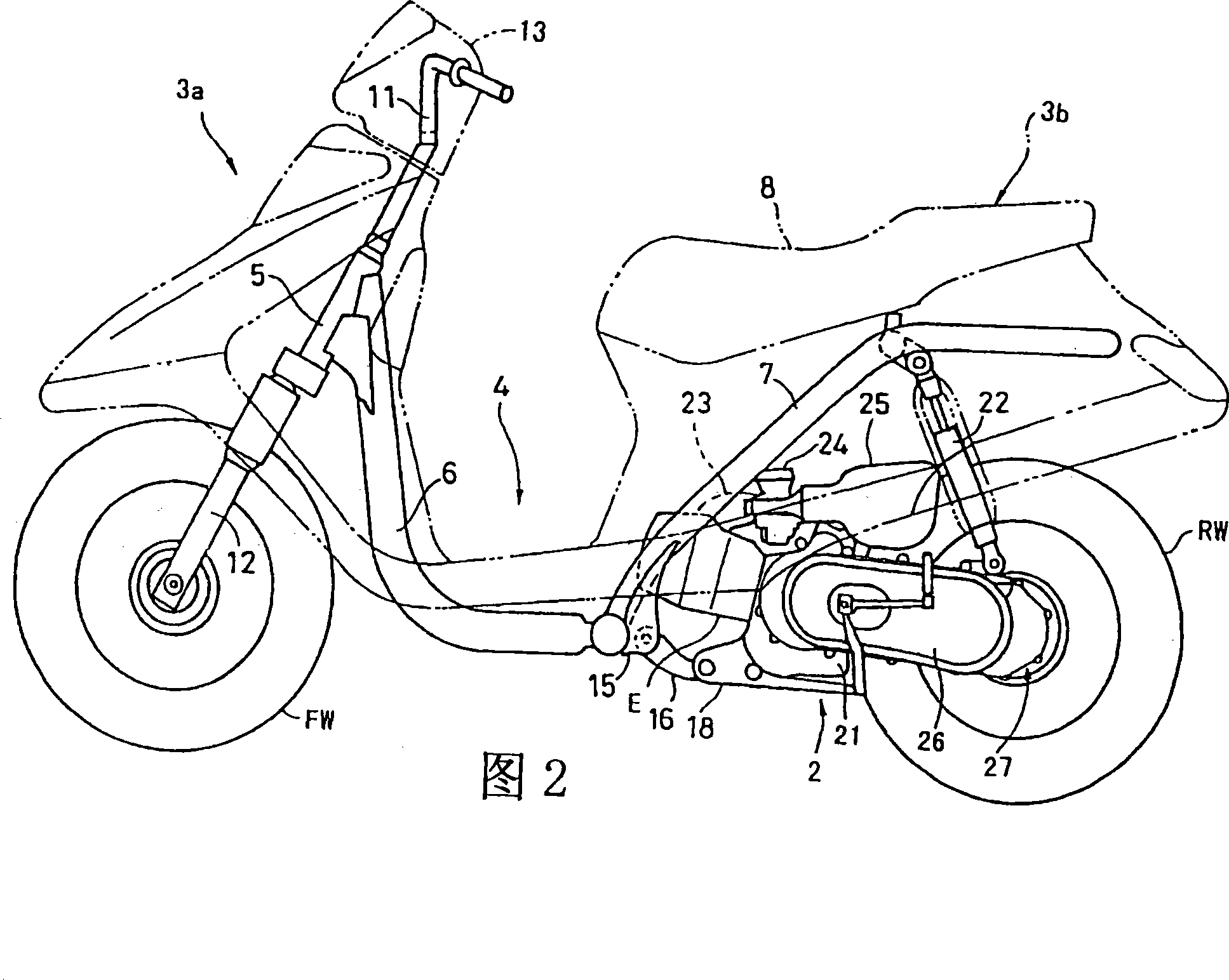
[0041] An embodiment of the present invention will be described below with reference to the drawings. Fig. 2 is a side perspective view of a scooter-type motorcycle equipped with a starter-generator according to an embodiment of the present invention. In this figure, the vehicle body front part 3a and the vehicle body rear part 3b are connected by the low floor part 4, and the vehicle body frame constituting the vehicle body frame mainly includes a downpipe 6 and a main pipe 7. A seat 8 is arranged above a fuel tank and a storage box (both not shown) supported by the main pipe 7 .

[0042] A handle 11 extending upward and a front fork 12 extending downward are rotatably supported on a steering head 5 at the front of the vehicle body, and a front wheel FW is pivotally supported on the lower end of the front fork 12 . The upper part of the handle 11 is covered with a handle cover 13 containing the instrument panel. A support 15 is provided at the lower end of the upright porti...


PUM


Abstract

To mount a rotor angle sensor and a pulser sensor of a brushless type electric rotating machine in a compact apace, and to improve the detection accuracy of an angular position of a rotor. A starter / generator 1 includes a stator 50 disposed around a crankshaft 201, and an outer rotor 60 which is fixed to the crankshaft 201 and which has a magnet member 62 facing to the outer periphery of the stator 50. A rotor angle sensor 29 and a pulser sensor 30 integrally contained in a sensor case 28 are provided on an inner peripheral surface of the stator 50. Magnet rings 33 are inserted in an outer peripheral portion of a hub 60a of the rotor 60. Since the rotor angle sensor 29 and the pulser 30 are integrally disposed, the sensor case 28 containing these sensors 29 and 30 can be miniaturized. Further, since the rotor angle 29 is mounted on the stator 50, it is possible to improve the accuracy of a positional relation ship between the rotor angle sensor 29 and the stator 50 and hence to improve the detection accuracy of an angular position of the rotor 60 with respect to the stator 50.

Description

[0001] The patent application for the present invention is a divisional application of the invention patent application with the application date being April 3, 2001, the application number being 01112429.6, and the invention title being "starter and generator". technical field [0002] The present invention relates to a starter-cum-generator, and more particularly to a starter-cum-generator having a rotor angle sensor for controlling the energization time of a starter composed of a brushless motor and a pulse sensor for an ignition trigger (triga) of the engine. dynamo. Background technique [0003] The engine is provided with a pulse sensor as an ignition trigger, that is, a pulse pick-up device. Japanese Patent Laid-Open Publication No. 7-103119 discloses an engine in which a pick-up sensor is installed on the inner peripheral surface of the flywheel. on the outer circumference of the rotating flywheel. [0004] In addition, in a starter-generator composed of a magnetic...

Claims


Application Information

Patent Timeline
IPC IPC(8): F02P7/067
Inventor 坂本友和柴田和己生井邦明
Owner HONDA MOTOR CO LTD
Why Eureka
Try Eureka