
Automatic control method for RF amplifier gain based on varying electrical bridge principle

A technology of radio frequency amplifier and automatic gain control, which is applied in the direction of gain control, high-frequency amplifier, and amplification control, etc. It can solve the problems of complex gain control circuit, low gain control accuracy, and poor system reliability.

Inactive Publication Date: 2008-02-13
INST OF ELECTRONICS CHINESE ACAD OF SCI
View PDF0 Cites 7 Cited by
  • Summary
  • Abstract
  • Description
  • Claims
  • Application Information

AI Technical Summary

Problems solved by technology

[0008] In order to solve the problems of low gain control accuracy, complex gain control circuit, poor system reliability and high development cost of existing radio frequency amplifiers, the purpose of the present invention is to provide a high-precision control of radio frequency amplifier gain, simple circuit, high reliability, Develop a low-cost method for controlling the gain of radio frequency amplifiers based on the principle of deformed bridge

Method used


Image

  • Automatic control method for RF amplifier gain based on varying electrical bridge principle
  • Automatic control method for RF amplifier gain based on varying electrical bridge principle
  • Automatic control method for RF amplifier gain based on varying electrical bridge principle

Examples


Embodiment Construction

[0094] The present invention will be described in detail below in conjunction with the accompanying drawings. It should be pointed out that the described embodiments are only intended to understand the present invention, rather than limiting it in any way.

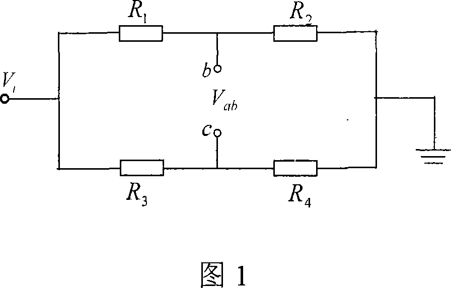
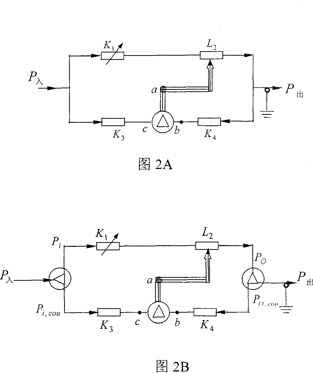
[0095] The present invention derives the modified electric bridge principle through the modification of the electric bridge principle. The principle of the deformed bridge is used in the closed-loop automatic gain control technology of the RF amplifier. It changes the proportional relationship of the resistance in the bridge principle into the proportional relationship of the gain. When the change of the output value of the differential circuit is zero, the gain of the deformed bridge circuit Obtain high precision stability.

[0096] The implementation mechanism of the method is:

[0097] (1). Using the exponential relationship of the V-I characteristics of Schottky radio frequency detection diodes, the exponential charac...


PUM


Abstract

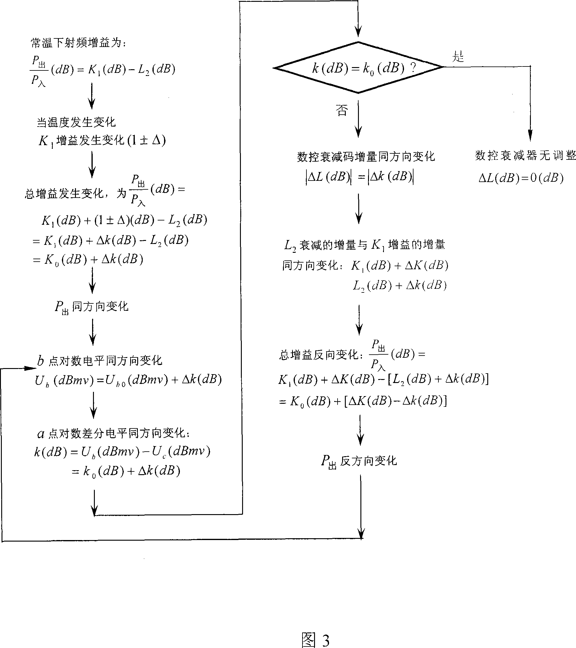
The invention relates to a method to control radio-frequency amplifier gain based on the deformation bridge theory. When the variance Delta Ubc of the differential voltage between a comparative end and a reference end equals to Delta k and also equals to 0, the high precision of the radio-frequency amplifier gain is stable, and the variance and the adjustment quantity of the radio frequency gain are balanced completely. When the variance and the adjustment quantity of the gain are balanced completely, parameters in the formula are as follows: Delta K1 (dB) is the variance of the radio frequency gain; Delta L2 (dB) is variance of attenuation of a digital control attenuator; Delta K3 (dB) is the signal gain of the reference end of an automatic gain control circuit; Delta K4(dB) is the signal gain of the comparative end of the automatic gain control circuit. The invention adopts the closed loop gain control proposal, and the circuit is simple. The gain control precision is high and is as high as 0.2 dB. The system structure is simple, and is designed rationally. The cost of development is low, and a lot of experimental expenses are saved. The invention solves the problems of poor stability of the radio-frequency amplifier gain, the complicated gain control circuit, low reliability of the system and high cost of development.

Description

technical field [0001] The invention belongs to the technical field of communication and electronic engineering, relates to an automatic gain control technology based on the principle of a modified electric bridge, and is used in a high-precision gain control system of a radio frequency amplifier. Background technique [0002] The existing RF amplifier gain stabilization schemes can be summarized as follows: [0003] Optical gain control, the circuit control scheme includes: the microwave input power is fed into the laser to generate an optical signal, which passes through an optical delay line and an optical gain controlled device to output an optical signal after gain adjustment, and then converts the optical signal into an electrical signal through a detector Output microwave power. Among them, the optical gain control circuit includes: optical splitter, optical fiber, electric optical attenuator, temperature monitoring, voltage comparison, data processing, and optical g...

Claims


Application Information

Patent Timeline
IPC IPC(8): H03G3/20H03F3/189
Inventor 梁淮宁
Owner INST OF ELECTRONICS CHINESE ACAD OF SCI
Learn More