
Fluid outlet metering valve

A quantitative valve and fluid technology, applied in valve devices, engine components, mechanical equipment, etc., can solve problems such as loss of elasticity of sealing rings, inability of quantitative cavity and valve stem outlet, and quantitative valve failure.

Inactive Publication Date: 2008-02-13
倚天(南京)金属制品有限公司
View PDF1 Cites 1 Cited by
  • Summary
  • Abstract
  • Description
  • Claims
  • Application Information

AI Technical Summary

Problems solved by technology

[0004] 1. When the gas composition in the gas tank is different (the gas density is different) or the work object is different (such as different nail specifications or nail types, such as cement nails and steel, decorative mosquito nails, etc.), it is often necessary Change the volume of the gas storage ring in the quantitative valve to adjust the amount of gas output at one time. The integral gas storage ring in the existing quantitative valve is closely matched with the valve body, and the manufacturing cost is high.
[0005] 2. Since the valve stem and the outer end of the gas storage ring are only sealed with an interference-fit rubber ring, during use, the reciprocating movement of the valve stem will have a pulling effect on the sealing ring, which will affect the quantitative accuracy and reliability of the quantitative valve.
In addition, this reciprocating traction makes the sealing ring easy to lose elasticity due to fatigue and become flexible
When its elastic hardness drops to a certain level, even with the movement of the valve stem, the dosing chamber and the air outlet of the valve stem will not be able to communicate, making the dosing valve lose its function
[0006] 3. The valve body is made of high-hardness plastics such as polyacrylamide. Due to manufacturing errors, it is impossible to ensure an ideal sealing fit between the air inlet hole and the air outlet ejector pin on the air tank. As a result, leakage will occur and affect the air pressure. tank performance

Method used


Image

  • Fluid outlet metering valve

Examples


Embodiment 1

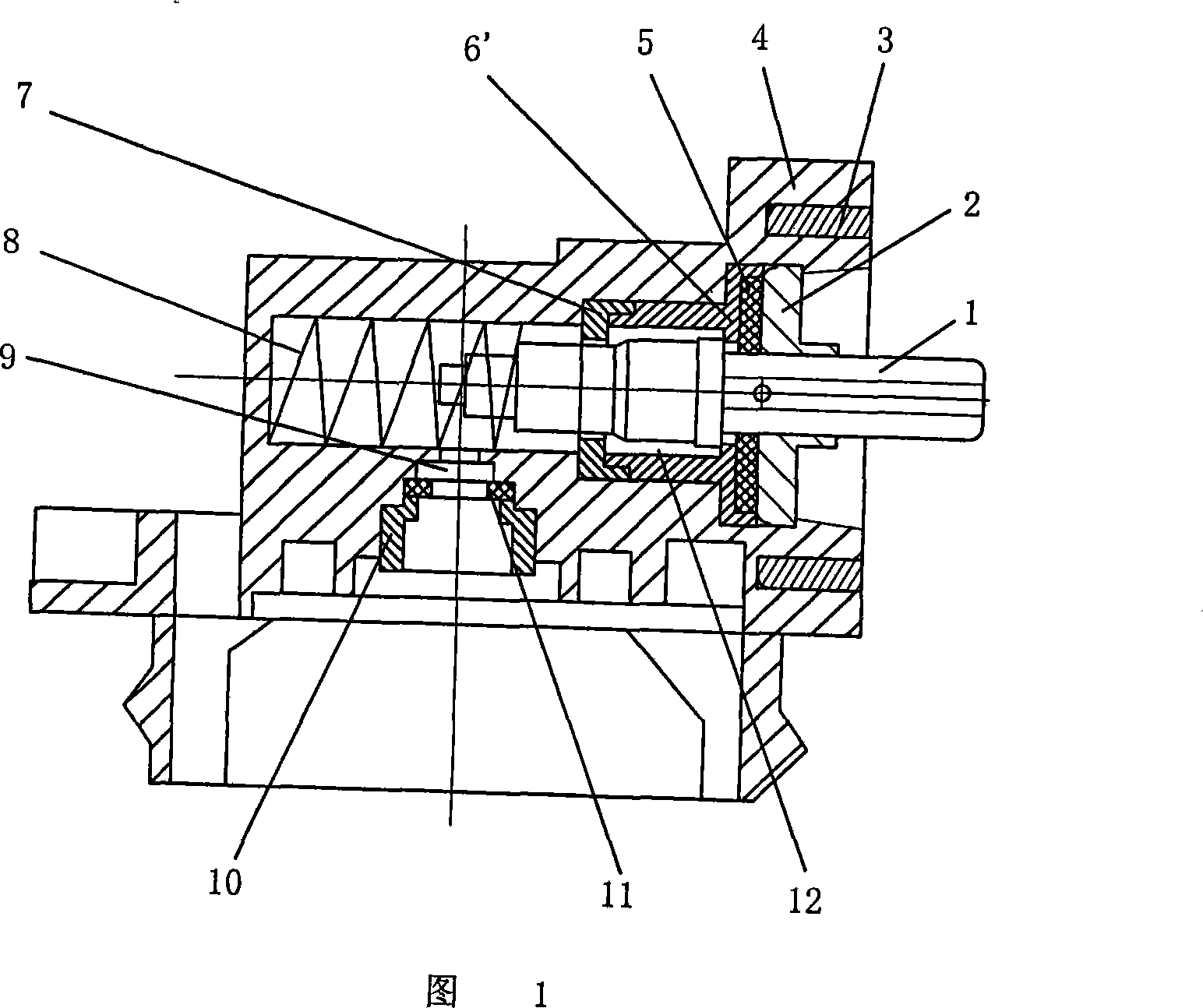
[0018] The fluid output quantitative valve of this embodiment is shown in Figure 1, and is a quantitative valve suitable for matching with a gas tank. The lower part of the valve body 4 is made into a cap shape matching the end of the gas tank, and the upper part is formed with a horizontal valve stem hole. Shaped gas storage ring. The gas storage ring is formed by inserting an inner gas storage ring 7 and an outer gas storage ring 6'. Wherein, one side of the inner gas storage ring 7 forms a circumferential flanging, which is bowl-bottom-shaped and made of polytetrafluoroethylene. The outer gas storage ring 6' is made of ordinary plastic, and is in the shape of a sleeve. The outer end surface of the edge is formed with a flat-bottomed depression, and the rubber sealing ring 5 is embedded in the depression, so that the inner end surface of the sealing ring leans on the concave end surface of the outer gas storage ring 6'. The outer end of the rubber sealing ring 5 leans aga...


PUM


Abstract

The invention relates to a fluid output metering valve and belongs to the valve control technical field. The metering valve comprises a valve body equipped with a valve rod hole and an air inlet hole. The middle section of the valve rod hole communicates with the air inlet hole, and an air storage ring is embedded at the external end of the valve rod hole. A valve rod goes through the air storage ring. An air outlet hole is made at the external end of the valve rod, and the internal end of the valve rod relies on an elastic part at the bottom of the valve rod hole. When the valve rod is at the position of jacking outwards, the air inlet hole of the valve body communicates with a metering chamber, and the metering chamber and the air outlet hole of the valve rod are blocked. When the valve rod is at the position of pressing inwards, the air inlet hole of the valve body and the metering chamber are blocked, and the metering chamber communicates with the air outlet hole of the valve rod. The air storage ring consists of an internal air storage ring and an external air storage ring, which are inserted and embedded. A typical structure is that the external side of the internal air storage ring forms circumferential flanges, which are bowl-bottom shape; the external air storage ring is cylindrical, and circumferential embedded edges are embedded and inserted at the internal end. When the capacity of the metering chamber is to be changed, only the external air storage ring has to be replaced properly. Thus, the valve is provided with an economic cost, and the installation and dismantlement is quite convenient.

Description

technical field [0001] The invention relates to a fluid control valve, in particular to a quantitative valve matched with a combustible gas storage tank, and belongs to the technical field of valve control for combustion appliances. Background technique [0002] According to the applicant's understanding, the typical structure of the metering valve matched with the combustible gas storage tank is as disclosed in US Patent No. 6,302,297. The bowl-shaped air storage ring passes through the valve stem. The outer end of the valve stem is shaped with an air outlet, and the inner end leans against the spring. In use, the valve stem has a first and a second position. When the valve stem is in the first position pushed outward under the action of the spring, the air inlet hole of the valve body communicates with the quantitative cavity, while the quantitative cavity and the air outlet hole of the valve stem are blocked, so that the quantitative cavity is filled with gas; When the ...

Claims


Application Information

Patent Timeline
IPC IPC(8): F16K13/00
Inventor 周润亚李明
Owner 倚天(南京)金属制品有限公司
Learn More