
Movement decoupling spherical surface rotating paralleling mechanism can be used as the robot wrist joint

A robot wrist and joint technology, applied in the fields of shoulder, robot wrist and waist joint, can solve the problems of complex parallel mechanism control, weak coupling of pose parameters, change of pose parameters, etc., to achieve fast motion response, simple control, and rotational inertia. small effect

Inactive Publication Date: 2008-02-06
DONGHUA UNIV
View PDF1 Cites 19 Cited by
  • Summary
  • Abstract
  • Description
  • Claims
  • Application Information

AI Technical Summary

Problems solved by technology

In the "sun tracking device based on spherical mechanism" reported in Chinese patent document CN03258423.7, a three-degree-of-freedom spherical mechanism is used, but its three rotations are fully coupled, that is, it cannot be decoupled; resulting in complicated control of the parallel mechanism and difficult calibration. And restrict the improvement of precision
The two-degree-of-freedom spherical mechanism proposed by US patent US00596699IA can only be decoupled instantaneously at the initial position, and cannot be decoupled at other positions
Literature [Hang Lubin, Wang Yan, Wu Jun, etc. Research on decoupling conditions of spherical parallel mechanism based on topology decoupling criterion [J]. Chinese Journal of Mechanical Engineering, 2005, Vol.41, No.9: pp28-32] proposed a Partially decoupled 3-RRR spherical rotation mechanism, but because the pose parameters still have weak coupling, controlling one pose parameter will cause other pose parameters to change at the same time
The literature on the invention of the three-degree-of-freedom spherical mechanism that can be decoupled has not yet been retrieved

Method used


Image

  • Movement decoupling spherical surface rotating paralleling mechanism can be used as the robot wrist joint
  • Movement decoupling spherical surface rotating paralleling mechanism can be used as the robot wrist joint

Examples


Embodiment Construction

[0015] Below in conjunction with specific embodiment, further illustrate the present invention. It should be understood that these examples are only used to illustrate the present invention and are not intended to limit the scope of the present invention. In addition, it should be understood that after reading the teachings of the present invention, those skilled in the art can make various changes or modifications to the present invention, and these equivalent forms also fall within the scope defined by the appended claims of the present application.

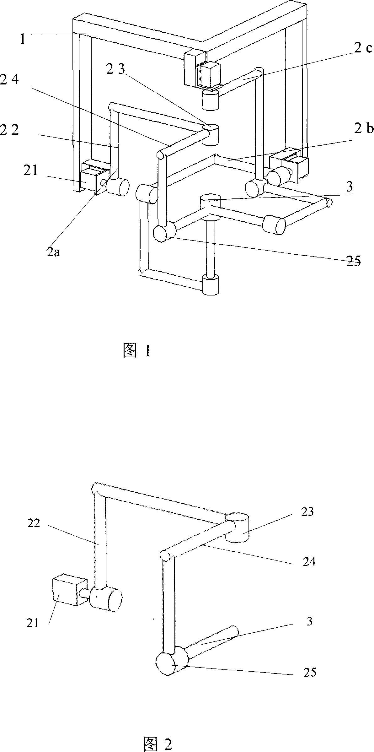
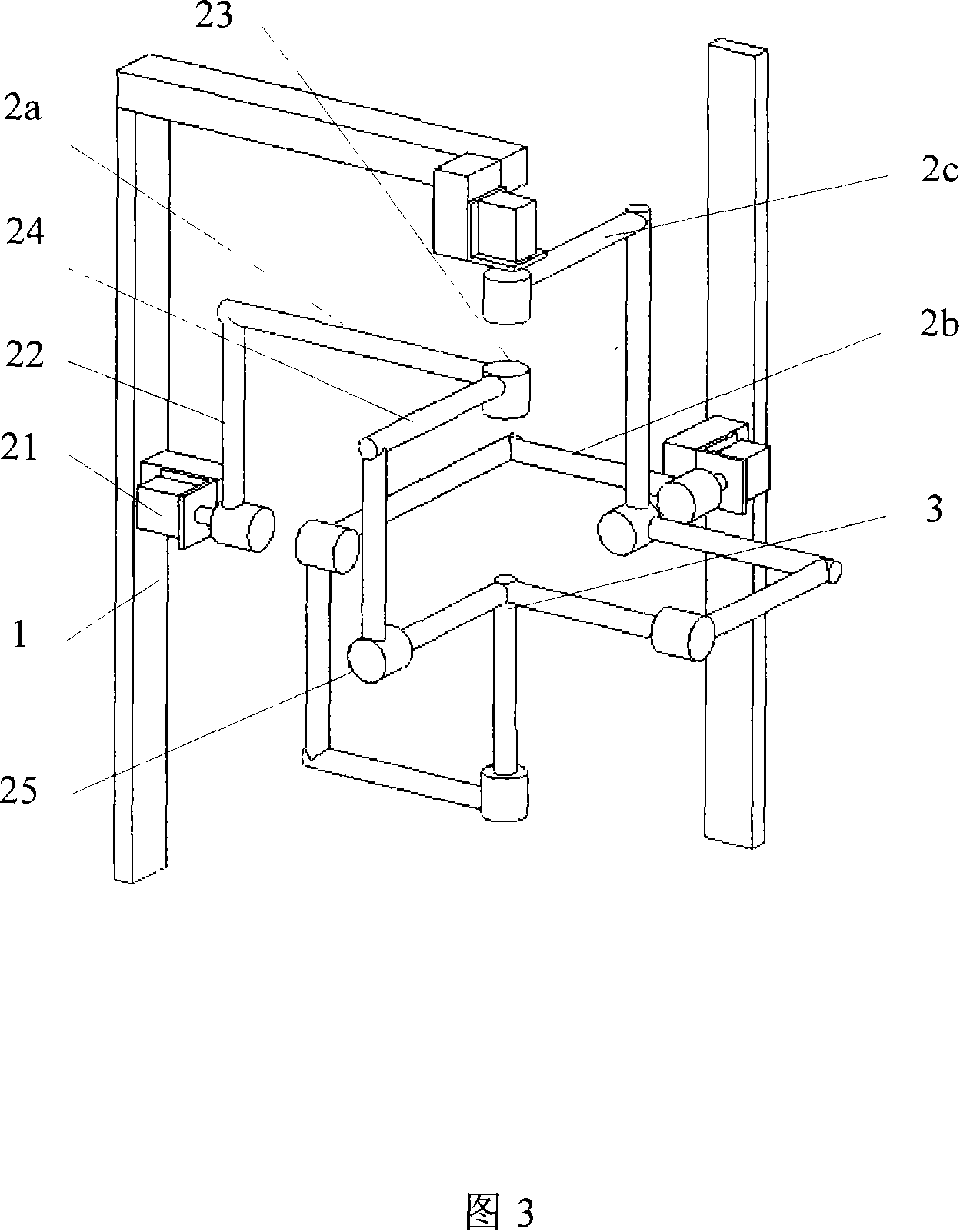
[0016] As shown in Figures 1 and 3, the present invention can be used as a motion decoupling spherical rotation parallel mechanism for the wrist joint of a robot. The three kinematic branch chains 2a, 2b, 2c are combined. The kinematic branch chains 2a, 2b, and 2c are all composed of three rotating pairs and rods between them. The active pairs of the three kinematic branch chains 2a, 2b, and 2c are distributed orthogonally to ...


PUM


Abstract

The invention discloses a kinematic decoupling spherical rotation parallel mechanism that can be used as a robot wrist, comprising a rack (1), a movable platform (3) and three kinematic branch chains (2a), (2b) and (2c) which are fixed between the rack and the movable platform and are in the same structural type. Each kinematic branch chain comprises three revolute pairs and rods among the three revolute pairs, primary pairs of the three revolute pairs are distributed via positive crossing and the axes of all kinematic pairs converge to one point. Rotation motors of the three kinematic branch chains drive to realize that the movable platform rotates around the sphere surface of the axes convergence point of the rotation pairs and outputs. The initial end of each kinematic branch chain is motor-driven. The parallel mechanism relating to the invention has the advantages such as kinematic decoupling, simple in structure, easy to control and low in cost, and can be used in the fields such as robot wrist, shoulder joint, satellite positioning and advanced manufacturing.

Description

technical field [0001] The invention relates to an industrial robot, in particular to wrist, shoulder and waist joints of the robot. Background technique [0002] Industrial robots are usually composed of three parts: mechanical system, control system and intelligent system. The mechanical system is further divided into an actuator and a drive mechanism. The actuator is generally composed of a hand, a wrist, an arm, a waist and a frame. The robot wrist (wrist) is the connection part between the arm and the hand, the adjustment mechanism of the robot, and the most complicated part in the industrial robot manipulator. Wrists can be divided into single-degree-of-freedom wrists, two-degree-of-freedom wrists, and three-degree-of-freedom wrists according to the number of degrees of freedom. The wrist is located at the surgical end of the arm, requiring a compact structure and light weight; in order to allow the wrist to be in any direction in space and perform various operations...

Claims


Application Information

Patent Timeline
Patent Type & Authority Applications(China)
IPC IPC(8): B25J17/00B25J9/08
Inventor 杨建国李蓓智张帆
Owner DONGHUA UNIV
Learn More