Optical connecting parts and optical connecting structure
A technology for optical connection and connection components, which is applied in the field of optical connection components and optical connection structures. It can solve the problems that the shell and metal ring occupy a large space, the processing of optical transmission media is difficult, and the connection is difficult to stabilize, so as to shorten the connection time. , Easy alignment, and the effect of reducing the number of parts
- Summary
- Abstract
- Description
- Claims
- Application Information
AI Technical Summary
Problems solved by technology
Method used
Image

Examples
Embodiment approach 1
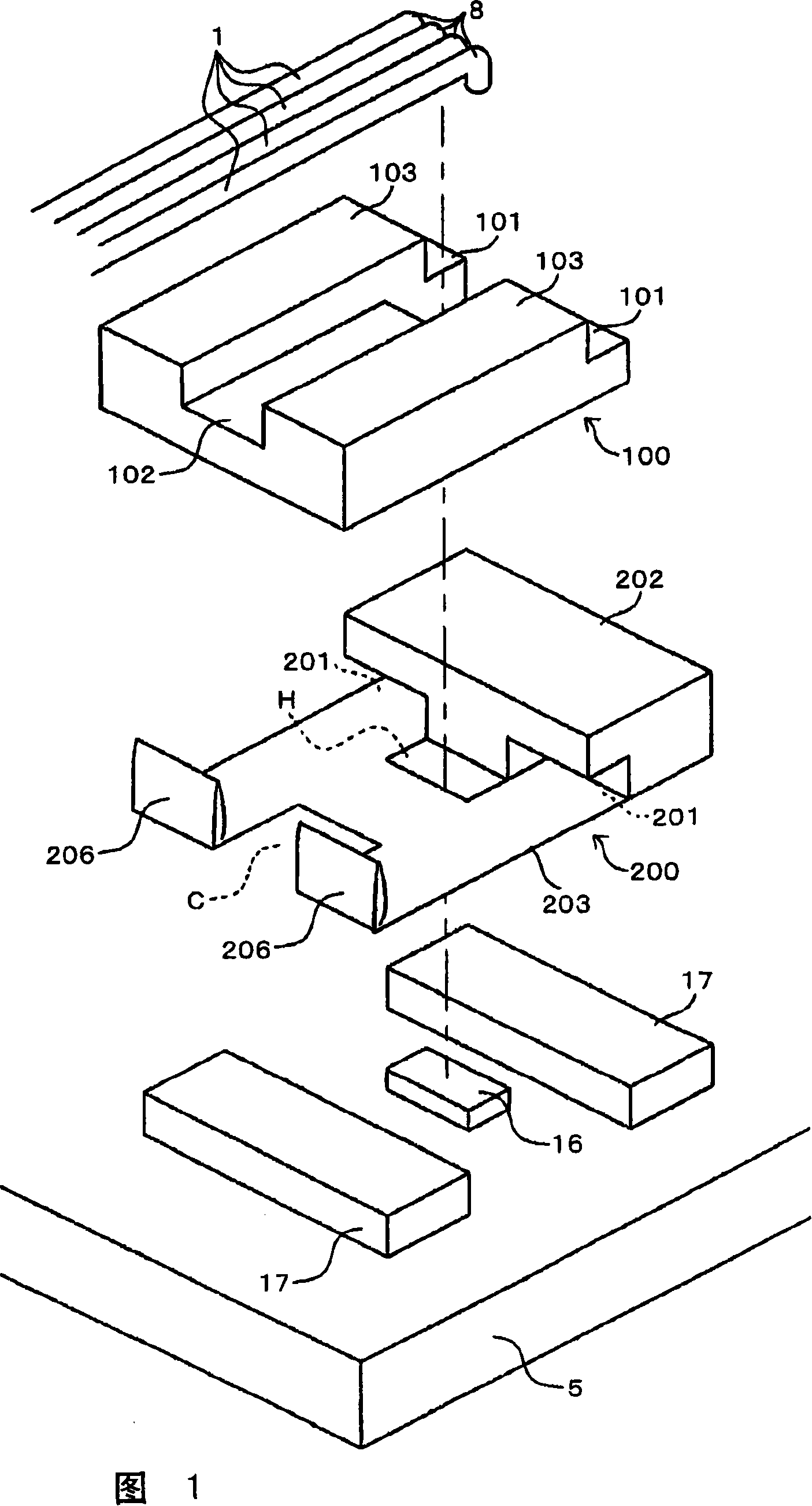
[0113] First, an optical connection component according to Embodiment 1 and an optical connection structure using the same will be described with reference to FIGS. 1 to 3 .
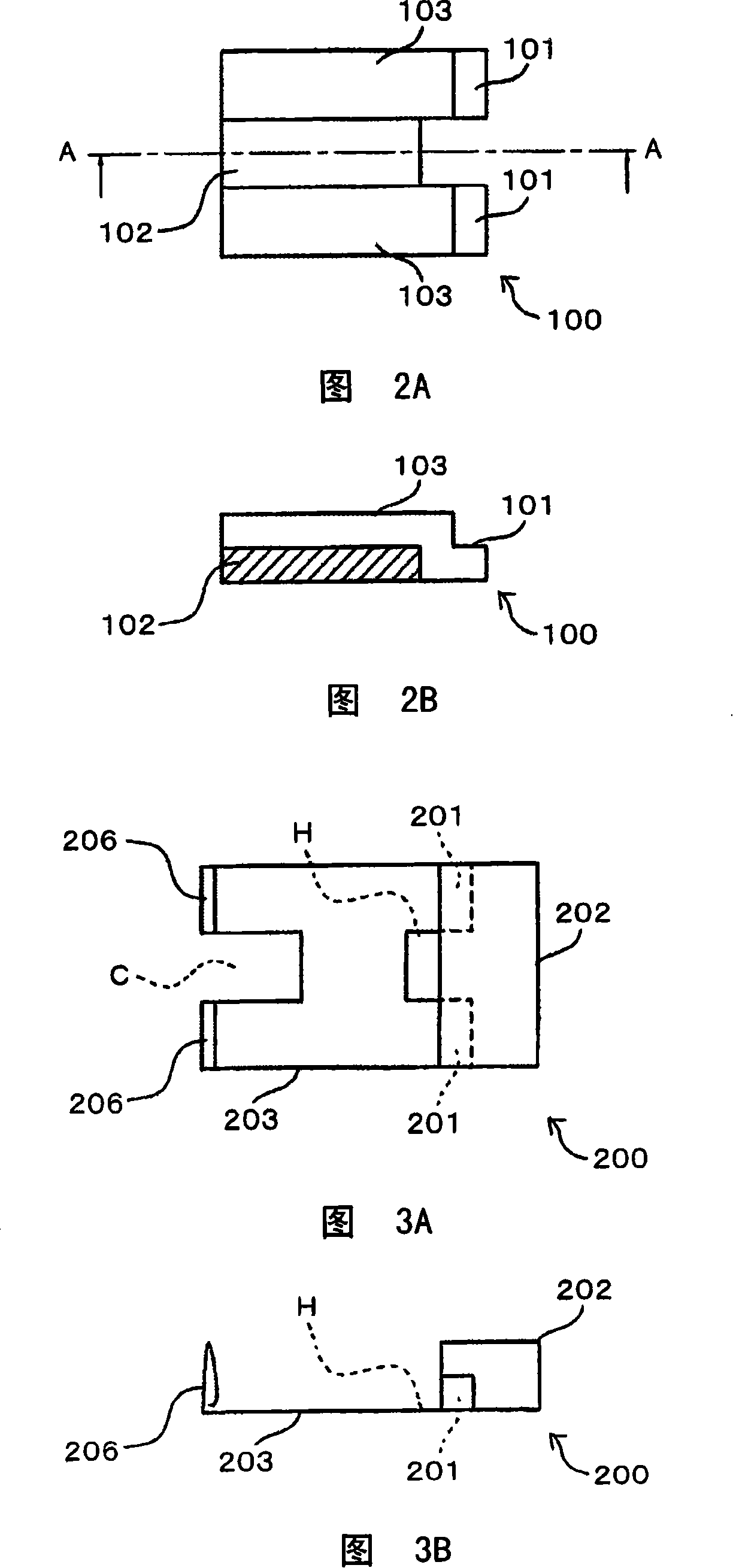
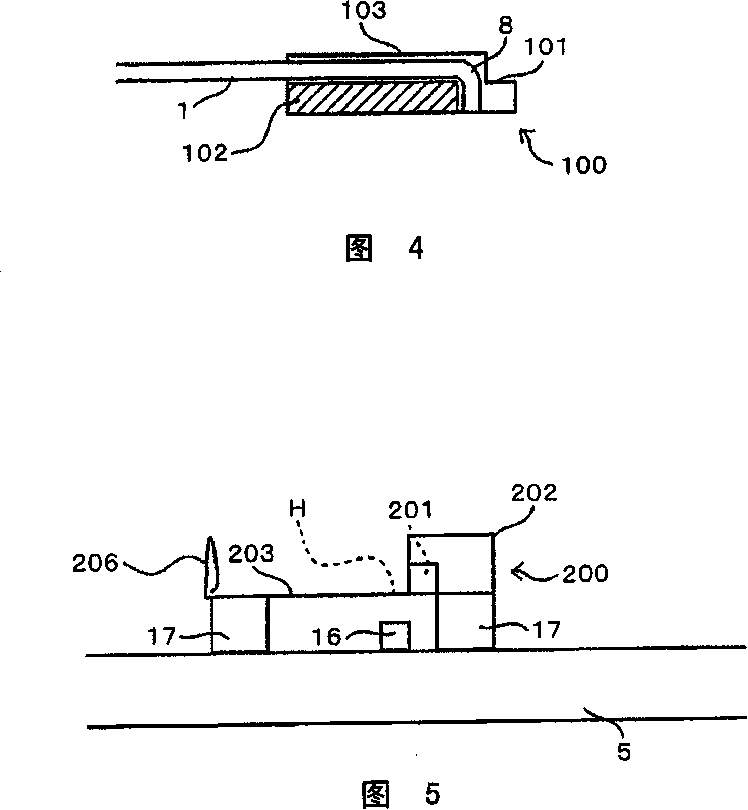
[0114] Fig. 1 is an exploded perspective view of the optical connection structure of Embodiment 1, Fig. 2 is a diagram showing a connection member having a convex portion of Embodiment 1, (a) is a top view, (b) is a view cut along line A-A, and Fig. 3 is a diagram showing (a) is a plan view, and (b) is a side view of the connection member with a recessed part of Embodiment 1.
[0115] 1 is an optical transmission medium such as an optical fiber, 5 is a substrate, 8 is a bending part, 16 is an optical functional part such as a surface emitting laser, 17 is a base, 100 is a connecting part with a convex part, 101 is a convex part, and 102 is a holding part. The holding part of the optical transmission medium 1, 103 is a protruding part, 200 is a connecting member with a concave part, 201 is a concave part,...
Embodiment approach 2
[0137] Next, an optical connection component according to Embodiment 2 and an optical connection structure using the same will be described with reference to FIGS. 7 and 8 .
[0138] 7 is a diagram showing a connecting member having a convex portion according to Embodiment 2, (a) is a plan view, (b) is a cross-sectional view along line B-B, and (c) is a perspective view. FIG. 8 shows a connection having a convex portion according to Embodiment 2. A cross-sectional view of the state in which the part holds the light-transmitting medium.
[0139] 100a is a connecting member having a convex part, and 102a is a holding part.
[0140] Embodiment 2 is the same as Embodiment 1 except that the connection member 100 with protrusions in Embodiment 1 is replaced with connection member 100 a with protrusions, and the optical transmission medium 1 is bent 180 degrees.
[0141] As shown in FIG. 7 , the holding portion 102 a is hollowly supported, and the connecting member 100 a having a co...
Embodiment approach 3
[0144] Next, an optical connection component according to Embodiment 3 and an optical connection structure using the same will be described with reference to FIGS. 9 and 10 .
[0145] 9 is a view showing a connecting member having a convex portion according to Embodiment 3, (a) is a plan view, (b) is a cross-sectional view along line C-C, and FIG. The cross-sectional view of the process, (a) is the figure before maintaining, (b) is the figure being maintained, and (c) is the figure after maintaining.
[0146] 100b is a connecting member having a convex part, 106 is a bearing part, 107 is an eccentric cam, and 108 is a rotating shaft.
[0147] Embodiment 3 is the same as Embodiment 1 except that the connecting member 100 having a convex portion in Embodiment 1 is replaced with a connecting member 100b having a convex portion.
[0148] As shown in FIG. 9 , the connecting member 100 b having a convex portion has a bearing portion 106 , an eccentric cam 107 , and a rotating shaft...
PUM
 Abstract
Description
Claims
Application Information
 - R&D
- Intellectual Property
- Life Sciences
- Materials
- Tech Scout
- Unparalleled Data Quality
- Higher Quality Content
- 60% Fewer Hallucinations
Browse by: Latest US Patents, China's latest patents, Technical Efficacy Thesaurus, Application Domain, Technology Topic, Popular Technical Reports.
© 2025 PatSnap. All rights reserved.Legal|Privacy policy|Modern Slavery Act Transparency Statement|Sitemap|About US| Contact US: help@patsnap.com