Panel Antennas for RFID Tags

A technology of radio frequency identification tags and flat antennas, applied in the field of flat antennas of radio frequency identification tags, can solve problems such as inability to be widely used, inability to take into account miniaturization and impedance matching, and recognition distance limitations

Inactive Publication Date: 2011-12-07
TATUNG COMPANY +1
View PDF0 Cites 0 Cited by
  • Summary
  • Abstract
  • Description
  • Claims
  • Application Information

AI Technical Summary

Problems solved by technology

However, although the traditional panel antenna 200 achieves the purpose of miniaturization, the 50-ohm matching concept it adopts cannot achieve good impedance matching with the tag chip.
[0006] To sum up, the traditional panel antenna cannot take into account the purpose of miniaturization and impedance matching in application
In other words, when the radio frequency identification system uses the traditional panel antenna, the identification distance covered by it will be limited, and it cannot be widely used in other systems

Method used


Image

  • Panel Antennas for RFID Tags
  • Panel Antennas for RFID Tags
  • Panel Antennas for RFID Tags

Examples


Embodiment Construction

[0032] In order to meet the miniaturization and impedance matching required in the application of the radio frequency identification tag's planar antenna, the present invention obtains the optimal size of the fractal dipole antenna through repeated design and experimental results. Compared with the traditional panel antenna, the panel antenna of the present invention not only has a miniaturized appearance, but also can effectively improve the identification distance of the radio frequency identification system. The panel antennas of the present invention will be illustrated below, but they are not intended to limit the present invention. Those in the industry can slightly modify the following embodiments according to the spirit of the present invention, but they still fall within the scope of the present invention.

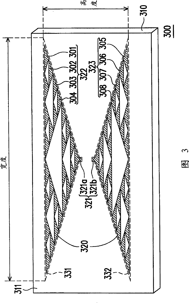
[0033] image 3 It is a structural schematic diagram of the planar antenna of the radio frequency identification tag according to an embodiment of the present inv...


PUM


Abstract

A flat panel antenna of a radio frequency identification tag is used for sending and receiving an electromagnetic signal. The planar antenna includes a dielectric plate and a fractal dipole antenna. The height of the fractal dipole antenna is 0.3 to 0.7 times the half wavelength of the electromagnetic signal, and the width of the fractal dipole antenna is 0.7 to 1.1 times the half wavelength of the electromagnetic signal. This panel antenna utilizes the optimized fractal dipole antenna size to achieve miniaturization and good matching.

Description

technical field [0001] The present invention relates to a panel antenna, and in particular to a panel antenna suitable for radio frequency identification (RFID) tags. Background technique [0002] In recent years, the radio frequency identification system has gradually replaced the existing barcode label system due to its advantages of non-contact identification, simultaneous reading of multiple labels, and data security. The radio frequency identification system has a wide range of applications, such as access control cards, leisure cards, plant identification chips, etc., and it can also be used in logistics control, library management, and medical drug management in the future. [0003] The RFID system mainly includes a reader system and a tag system. The code reading system uses electromagnetic signals to transmit label information to the labeling system. The tag system uses the flat panel antenna to send and receive electromagnetic signals, and uses the tag chip to ju...

Claims


Application Information

Patent Timeline
Patent Type & Authority Patents(China)
IPC IPC(8): H01Q1/38H01Q9/16G06K19/07
Inventor 黄启芳詹景晴
Owner TATUNG COMPANY
Why Eureka
Try Eureka