Coin selector
A selector, coin technology, applied in the direction of coin checking, coinless or similar appliances, coin inlet devices, etc.
- Summary
- Abstract
- Description
- Claims
- Application Information
AI Technical Summary
Problems solved by technology
Method used
Image


Examples
Embodiment 1
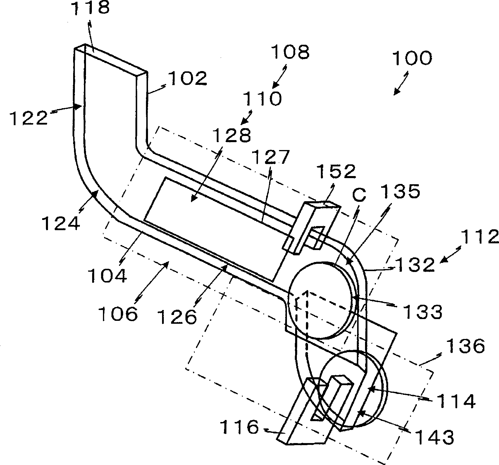
[0132] figure 1 It is a schematic perspective view of the coin selector of Example 1.
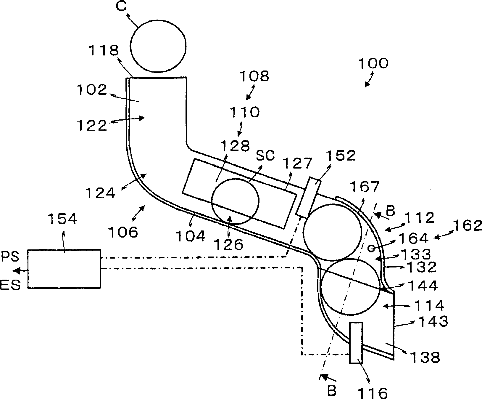
[0133] figure 2 It is a schematic front view of the coin selector of Embodiment 1.
[0134] image 3 is along figure 2 Sectional view of line B-B in middle.
[0135] Figure 4 It is a figure explaining the operation of the coin selector of Example 1.
[0136] Figure 5 is a timing chart for explaining the action of the first embodiment.
[0137] exist figure 1 Among them, the coin selector 100 includes: a plate-shaped main body 102, a guide rail 104 positioned at the bottom of the main body 102, a coin channel 106, a true-false judging device 108 disposed in the middle of the guide rail 104, that is, a diameter identification device 110, a moving direction changing device 112, a The coin detection channel 114 of the moving direction changing device 112 downstream, the second main body 138 ( image 3 , 4 ), and the coin sensor 116 disposed in the coin detection channel 114.
...
Embodiment 2
[0250] Image 6 is that of Example 2 and figure 2 The same cutaway view.
[0251] In Embodiment 2, the upper surface of the blocking member 174 of the pull-back prevention device 172 is made into an inclined guide surface 146 .
[0252] like Image 6 As shown, the stopper 174 of the pullback prevention device 172 is mounted on the fixed support shaft 145 directly above the upper end of the partition wall 142, and can pivot, and usually rotate due to its own weight.
[0253] Typically, the blocking member 174 is prevented from rotating by the upper end of the bulkhead 142 and forms an angle of about 45 degrees with respect to the second body 138 .
[0254] A front end of the blocking member 174 on one side of the second body 138 is in a zigzag shape.
[0255] Usually, the blocking member 174 is due to its own weight to Image 6 The clockwise rotation in the center is stopped due to being blocked by the upper end of the partition wall 142 .
[0256] In the stopped state, ...
Embodiment 3
[0263] Figure 7 It is the front view of the coin selector of Embodiment 3 of the present invention.
[0264] Figure 8 It is the rear view of the coin selector of Embodiment 3 of the present invention.
[0265] Figure 9 It is an exploded perspective view of the coin selector of Embodiment 3 of the present invention.
[0266] Figure 10 It is a front view of the coin selector according to Embodiment 3 of the present invention when the second body and the third body are removed.
[0267] Figure 11 It is the rear view of the third main body of the coin selector of Embodiment 3 of the present invention.
[0268] Figure 12 Yes Figure 7 A-A sectional view in .
[0269] Figure 13 Yes Figure 7 In the B-B sectional view, (A) is when accepting coins, and (B) is when rejecting coins.
[0270] Figure 14 Yes Figure 7 C-C cross-section in .
[0271] Figure 15 Yes Figure 7 The D-D profile in .
[0272] Figure 16 Yes Figure 7 The E-E cross-section in .
[027...
PUM
 Abstract
Description
Claims
Application Information
 - R&D
- Intellectual Property
- Life Sciences
- Materials
- Tech Scout
- Unparalleled Data Quality
- Higher Quality Content
- 60% Fewer Hallucinations
Browse by: Latest US Patents, China's latest patents, Technical Efficacy Thesaurus, Application Domain, Technology Topic, Popular Technical Reports.
© 2025 PatSnap. All rights reserved.Legal|Privacy policy|Modern Slavery Act Transparency Statement|Sitemap|About US| Contact US: help@patsnap.com