Supersonic speed nozzle for laser cutting
A supersonic nozzle and laser cutting technology, which is applied in laser welding equipment, welding equipment, metal processing equipment, etc., can solve the problems that it is difficult to ensure the stability of supersonic flow, the continuity of the boundary layer on the wall surface, and the difficulty of processing. , to achieve the effect of improving cutting quality and cutting efficiency, good cutting effect and good processing quality
Inactive Publication Date: 2008-01-16
SHANGHAI JIAO TONG UNIV
View PDF1 Cites 14 Cited by
- Summary
- Abstract
- Description
- Claims
- Application Information
AI Technical Summary
Problems solved by technology
However, the design of the above-mentioned supersonic nozzle, because the inner wall of the divergent section of the supersonic region of the nozzle is a combination of straight lines and high-order curves, not only increases the difficulty of processing, but also makes it difficult to ensure the stability of t
Method used
View moreImage
Smart ImageViewing Examples
Examples
 PUM
 Abstract
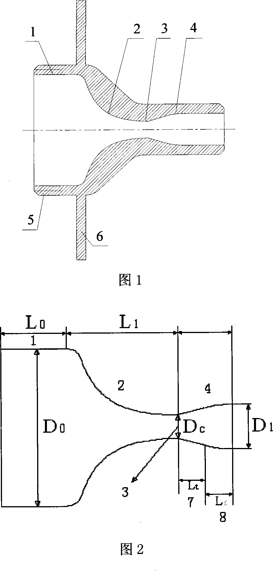
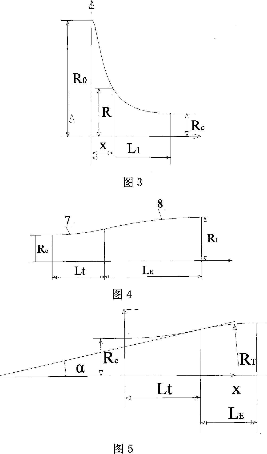
Disclosed is a supersonic speed nozzle used in laser cutting in the technical field of mechanical laser processing, comprising parallel sections, a contraction section, a laryngeal, and a divergent section, all of which are communicated as a whole. The laryngeal is a transitional cross section arranged between the contraction section and the divergent section. The divergent section comprises a first section and a second section, which assure the boundary layers on the wall of the supersonic speed area not disconnected. The first section and the second section are smoothly connected; the first section is arranged between the laryngeal and the second section; the first section is determined by a Blunt-Meier expansion line in the isentropic condition; the second section adopts an arc of large diameter to make the gradient of a curve reduced to 0 according to a simplified Hall designing method. When the invention is used to cut the laser, the cutting effect is good with fast speed and good cutting quality, and the cut lower edge does not have slag hanging. Particularly, when processing metal that is difficult to be processed, the invention can effectively blow away melt metal and other slag of high viscosity, and thus improves the cut quality and efficiency.
Description
technical field [0001] The invention relates to a nozzle in the field of mechanical technology, in particular to a supersonic nozzle for laser cutting. Background technique [0002] In the laser cutting process, the nozzle is mainly used as a discharge channel for the laser beam and auxiliary gas, and is an important part to realize laser cutting. The laser cutting process is the result of the interaction between the high-energy laser beam and the auxiliary gas. On the one hand, the high-energy beam melts or even vaporizes the processing material, and on the other hand, the auxiliary gas discharges the molten metal and part of the heat from the incision. Therefore, a reasonable nozzle structure can not only improve the processing capacity, but also limit the heat-affected zone to a small range, ensuring good processing quality. [0003] At present, there are two design structures for laser supersonic nozzles: one is the Laval type straight channel structure, and the other i...
Claims
Login to View More Application Information
Patent Timeline
 IPC IPC(8): B23K26/00B23K26/38B23K26/14
Inventor 胡俊郭绍刚何波罗磊
Owner SHANGHAI JIAO TONG UNIV
Features
- R&D
- Intellectual Property
- Life Sciences
- Materials
- Tech Scout
- Unparalleled Data Quality
- Higher Quality Content
- 60% Fewer Hallucinations
Learn More Browse by: Latest US Patents, China's latest patents, Technical Efficacy Thesaurus, Application Domain, Technology Topic, Popular Technical Reports.
© 2025 PatSnap. All rights reserved.Legal|Privacy policy|Modern Slavery Act Transparency Statement|Sitemap|About US| Contact US: help@patsnap.com


