
Laminated coil part

A technology of stacking coils and components, applied in the direction of coil manufacturing, electrical components, magnetic objects, etc., can solve the problems of inability to prevent the decrease of impedance |Z|

Inactive Publication Date: 2011-09-28
MURATA MFG CO LTD
View PDF1 Cites 0 Cited by
  • Summary
  • Abstract
  • Description
  • Claims
  • Application Information

AI Technical Summary

Problems solved by technology

However, this multilayer inductor cannot relax the stress generated by the difference in shrinkage between the coil conductor and the ferrite during sintering of the laminate, and cannot prevent the drop in impedance |Z|

Method used


Image

  • Laminated coil part
  • Laminated coil part
  • Laminated coil part

Examples


no. 1 Embodiment

[0020] (first embodiment, reference Figure 1 to Figure 6 )

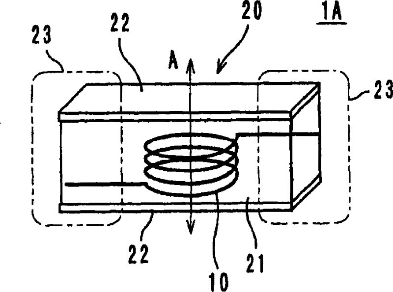
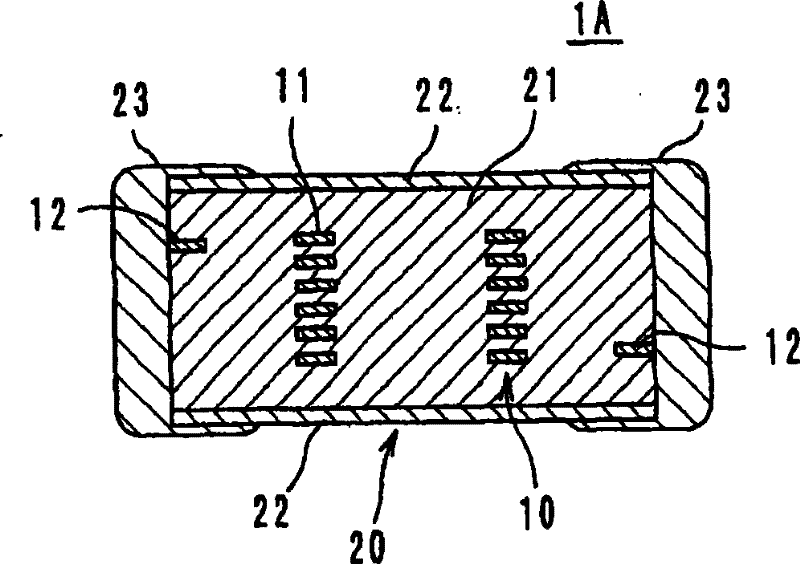
[0021] The laminated coil component 1A as the first embodiment of the present invention is as figure 1 As shown, there is a laminated body body 21 made of a first ferrite in which the coil 10 is provided, and a laminated body made of a second ferrite formed at both ends (upper and lower parts) in the coil axis direction A The end portion 22 , the left and right ends of the laminated body 20 are provided with external electrodes 23 . figure 2 Its section is shown.

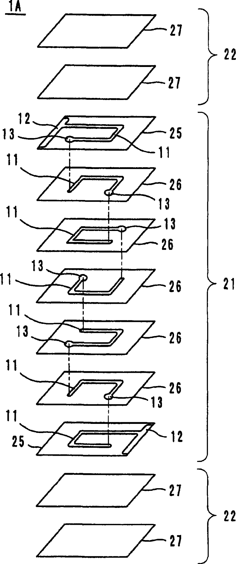
[0022] In more detail, as image 3 As shown, ferrite sheet 25 on which coil conductor 11 and lead-out electrode 12 are formed, ferrite sheet 26 on which coil conductor 11 is formed in a predetermined pattern, and blank ferrite sheet 27 are laminated. The sheets 25 and 26 are formed of first ferrite and form the above-mentioned main body 21 . The sheet 27 is formed of second ferrite, and forms the above-mentioned end portion 22 . Each coil conductor...

no. 2 Embodiment

[0041] (the second embodiment, refer to Figure 7 and Figure 8 )

[0042] Figure 7 In the illustrated laminated coil component 1B, the coil 50 is arranged in the laminated body body 61 formed of the first ferrite so that the coil 50 is arranged so that the coil axis direction A is parallel to the mounting surface 5, and the coil axis direction A is parallel to the mounting surface 5. The elements of the end portions of the laminated body 62 formed of the second ferrite are provided at both ends (the left and right end portions of the laminated body 60).

[0043] In more detail, as Figure 8 As shown, both end portions of the ferrite sheets 65 to 68 are formed of the second ferrite having a large shrinkage ratio, and the other portions are formed of the first ferrite. The coil conductor 51, the lead-out electrode 52, and the via-hole conductor 53 are formed in the ferrite sheet 65, the via-hole conductor 53 is formed in the ferrite sheet 66, and the coil conductor 51 and ...


PUM

PropertyMeasurementUnit
shrinkageaaaaaaaaaa

Abstract

A laminated coil part that realizes relaxing of any internal stress attributed to shrinkage of ferrite occurring at the time of firing of laminate, preventing any drop of impedance. There is provided a laminated coil part comprising laminate main part (21) of a first ferrite having coil (10) disposed in its interior and comprising laminate end parts (22) of a second ferrite formed at both end portions along the direction of coil axis (A). The first ferrite constituting the main part (21) and the second ferrite constituting the end parts (22) are different from each other in composition, and the shrinkage ratio at firing of the second ferrite is greater than that at firing of the first ferrite.

Description

technical field [0001] The present invention relates to a laminated coil component, and more particularly to a laminated coil component such as a chip inductor in which a coil is embedded in a laminate formed of ferrite. Background technique [0002] In general, a laminated coil element such as a chip inductor is formed by laminating a ferrite sheet and a coil conductor, and connecting the ends of the coil conductor through via-hole conductors to form a helical coil. Therefore, when this type of laminated coil element is used to cope with noise, it is desirable that the impedance |Z| is large, that is, the impedance |Z| is high and high performance is desired. However, in conventional laminated coil components, the ideal impedance |Z| cannot be obtained due to changes in characteristics due to shrinkage of ferrite during sintering. [0003] Patent Document 1 discloses a laminated inductor in which an adhesive layer is surface-bonded to the upper and lower surfaces of a ferr...

Claims


Application Information

Patent Timeline
Patent Type & Authority Patents(China)
IPC IPC(8): H01F17/00H01F41/04
CPCC04B2235/3281H01F17/0013H01F41/046H01F1/344C04B2235/3284C04B2235/3279C04B35/265
Inventor 岩崎友秀
Owner MURATA MFG CO LTD
Learn More