Underwater video detection device based on the omnidirectional vision
An all-round visual and video detection technology, applied in color TV parts, TV system parts, TV and other directions, can solve problems such as poor practicability, limited visual range, and difficult continuous video detection.
- Summary
- Abstract
- Description
- Claims
- Application Information
AI Technical Summary
Problems solved by technology
Method used
Image
Examples
Embodiment 1
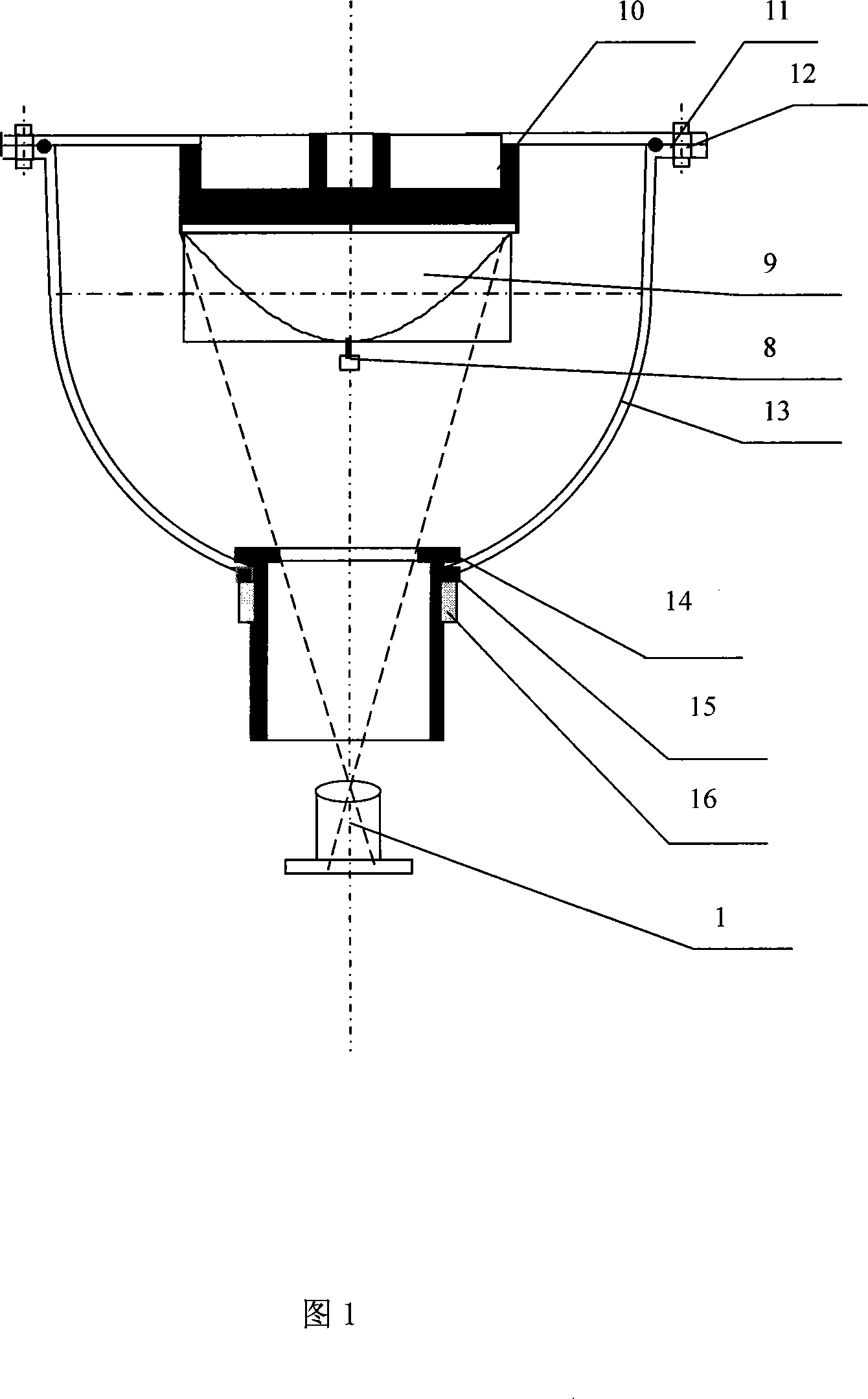
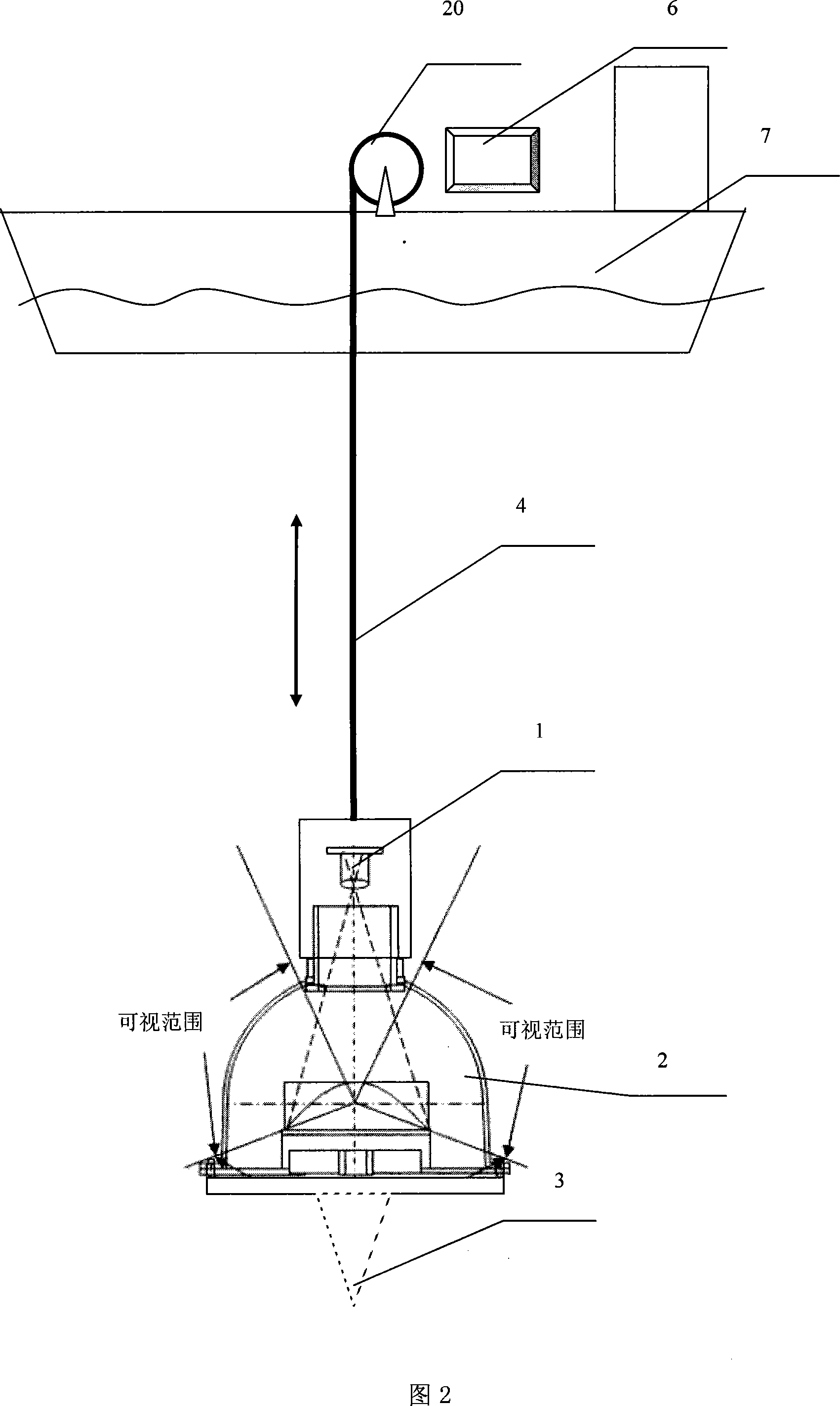
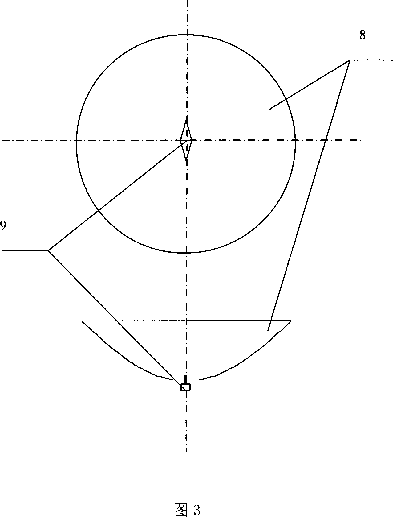
[0075] Referring to Figures 1 to 6, an underwater video detection device based on omnidirectional vision includes a visual sensor 2 for acquiring video of the water area to be detected and a microprocessor 6 for image processing. The visual sensor is installed On the lifting mechanism, the output of the visual sensor 2 is connected to a cable 4 for transmitting underwater video data, and the cable 4 is connected to a microprocessor 6, and the microprocessor 6 is connected to a display device. Processor 6 comprises: image data reading module, is used for reading the video image information that passes from vision sensor; Image data file storage module, is used for video image information is saved in storage unit by file mode; Image output module, It is used to output the processed image information to the display device; the visual sensor 2 is an omnidirectional visual sensor, including a catadioptric mirror 9 for vertically downward, a transparent outer cover 13, and an imaging...
Embodiment 2
[0123] With reference to Fig. 7, the remaining structural features of this embodiment are the same as Embodiment 1, and this embodiment is aimed at the underwater video detection of wide water area, needs to have underwater illuminating lamp as illumination source, to guarantee to provide enough in the range of underwater photography. The intensity of illumination ensures the quality of underwater video images, and a halogen tungsten lamp can be selected as the light source. Underwater lamps can be composed of stainless steel watertight protective shell, quartz glass watertight light window, leakage protection device and so on. This underwater lamp has the characteristics of long life, reliable operation and stable performance, and can work continuously for a long time. The lamps 19 can be evenly arranged on the periphery between the cone-shaped suppressor and the ODVS upper cover, and the lighting lamps are inclined outward at an angle, so that there is sufficient illuminatio...
Embodiment 3
[0125] Referring to Figures 1 to 6, the rest of the technical solutions are the same as in Embodiment 1. For relatively medium and large underwater cameras, a lifting mechanism can be used to deploy and recover underwater lamps and underwater cameras. Adjust the depth of lamps and cameras in the water to obtain the best underwater camera field of view. The lifting mechanism is mainly composed of two parts: the underwater part and the winch above the water. The underwater part includes a fixed frame on which an underwater camera and lighting lamps etc. are fixed. The water part includes motors, winches, steering pulleys, etc. The winch is connected on the rotating shaft of the motor, and the steel cable (cable) spans a turning pulley to connect the lifting frame with the winch, so that by turning the winch, the lifting mechanism can be raised and lowered, so that the camera can be positioned at an accurate position.
PUM
 Abstract
Description
Claims
Application Information
 - R&D
- Intellectual Property
- Life Sciences
- Materials
- Tech Scout
- Unparalleled Data Quality
- Higher Quality Content
- 60% Fewer Hallucinations
Browse by: Latest US Patents, China's latest patents, Technical Efficacy Thesaurus, Application Domain, Technology Topic, Popular Technical Reports.
© 2025 PatSnap. All rights reserved.Legal|Privacy policy|Modern Slavery Act Transparency Statement|Sitemap|About US| Contact US: help@patsnap.com


