


Quick Research
Generate reliable direction feasibility study reports for your R&D in just a few steps.

Technical Q&A
Discover and master advanced knowledge NOW. Basics, ideas, possibilities, all at once.

Find Solutions
As an expert in R&D theories, this can generate solutions to your technical problems instantly.

Evaluate Feasibility
Analyze your overall solution with one click, know your potential R&D risks in advance.

Monitor Landscape
Get weekly tech updates, stay abreast of the latest tech innovations and key insights.
Fan, motor and its shell
A shell and fan technology, applied in the field of motors, shells, and fans, can solve problems such as the inability to completely eliminate stress effects, and achieve the effect of reducing production costs
- Summary
- Abstract
- Description
- Claims
- Application Information
AI Technical Summary
Problems solved by technology
Method used
Image


Examples
Embodiment Construction
[0033] A fan, a motor and its housing according to a preferred embodiment of the present invention will be described below with reference to related drawings, wherein the same components will be denoted by the same reference numerals.
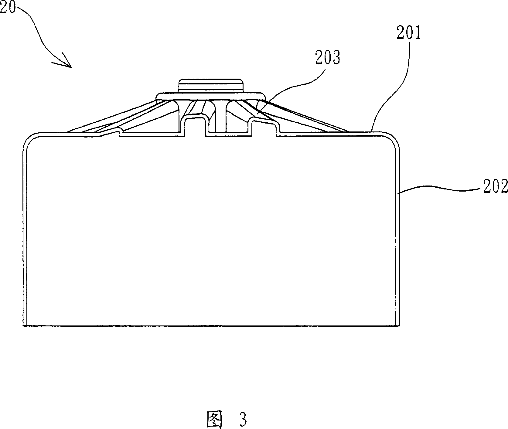
[0034] Referring to FIG. 2 , a housing 20 according to a preferred embodiment of the present invention includes a top 201 and a wall 202 , wherein the wall 202 is connected to the periphery of the top 201 . The housing 20 of this embodiment can be applied to the base of a motor or the hub of a fan.
[0035] The top 201 is a surface for bearing external force. Here, the top 201 has a plurality of concave-convex structures 203 arranged around the central axis of the top 201 to increase the stress-bearing area of the top 201 . The wall thickness of these concave-convex structures 203 is substantially the same as the wall thickness of the top 201, that is, the wall thickness of these concave-convex structures 203 is approximately the same as the ...
PUM
 Abstract
Description
Claims
Application Information
 - R&D Engineer
- R&D Manager
- IP Professional
- Industry Leading Data Capabilities
- Powerful AI technology
- Patent DNA Extraction
Browse by: Latest US Patents, China's latest patents, Technical Efficacy Thesaurus, Application Domain, Technology Topic, Popular Technical Reports.
© 2024 PatSnap. All rights reserved.Legal|Privacy policy|Modern Slavery Act Transparency Statement|Sitemap|About US| Contact US: help@patsnap.com