
Unstable resonator automatic cavity-adjusting system and method using self-collimation feedback light path

An unstable cavity and self-collimation technology, applied in the field of lasers, can solve the problems of fresnel diffraction core formation, cumbersome adjustment, slow adjustment speed, etc., to achieve the improvement of output beam quality and energy extraction efficiency, guaranteeing Integrity, the effect of increasing precision

Active Publication Date: 2008-01-02
NAT UNIV OF DEFENSE TECH
View PDF0 Cites 27 Cited by
  • Summary
  • Abstract
  • Description
  • Claims
  • Application Information

AI Technical Summary

Problems solved by technology

[0004] (1) The spot on the focal plane is a multi-beam interference fringe formed by superposition of multiple beams. The distribution of the light field is complex, and the aberration of the output beam cannot be quantitatively judged. Only the tilt information of the output beam of the unstable cavity can be obtained. High-order aberrations such as spherical aberration and coma cannot be judged, so the tuning accuracy is not high;
[0005] (2) It is necessary to judge which mirror positions are offset based on experience, and multiple mirrors need to be adjusted repeatedly, so the adjustment is cumbersome and the adjustment speed is slow
[0006] (3) The method of opening small holes on the concave mirror not only increases the difficulty of mirror processing and the risk of thermal damage to the mirror, but also destroys the formation of the Fresnel diffraction nucleus of the unstable cavity, which is not conducive to the quality of the output beam of the unstable cavity improve

Method used


Image

  • Unstable resonator automatic cavity-adjusting system and method using self-collimation feedback light path
  • Unstable resonator automatic cavity-adjusting system and method using self-collimation feedback light path
  • Unstable resonator automatic cavity-adjusting system and method using self-collimation feedback light path

Examples


Embodiment 1

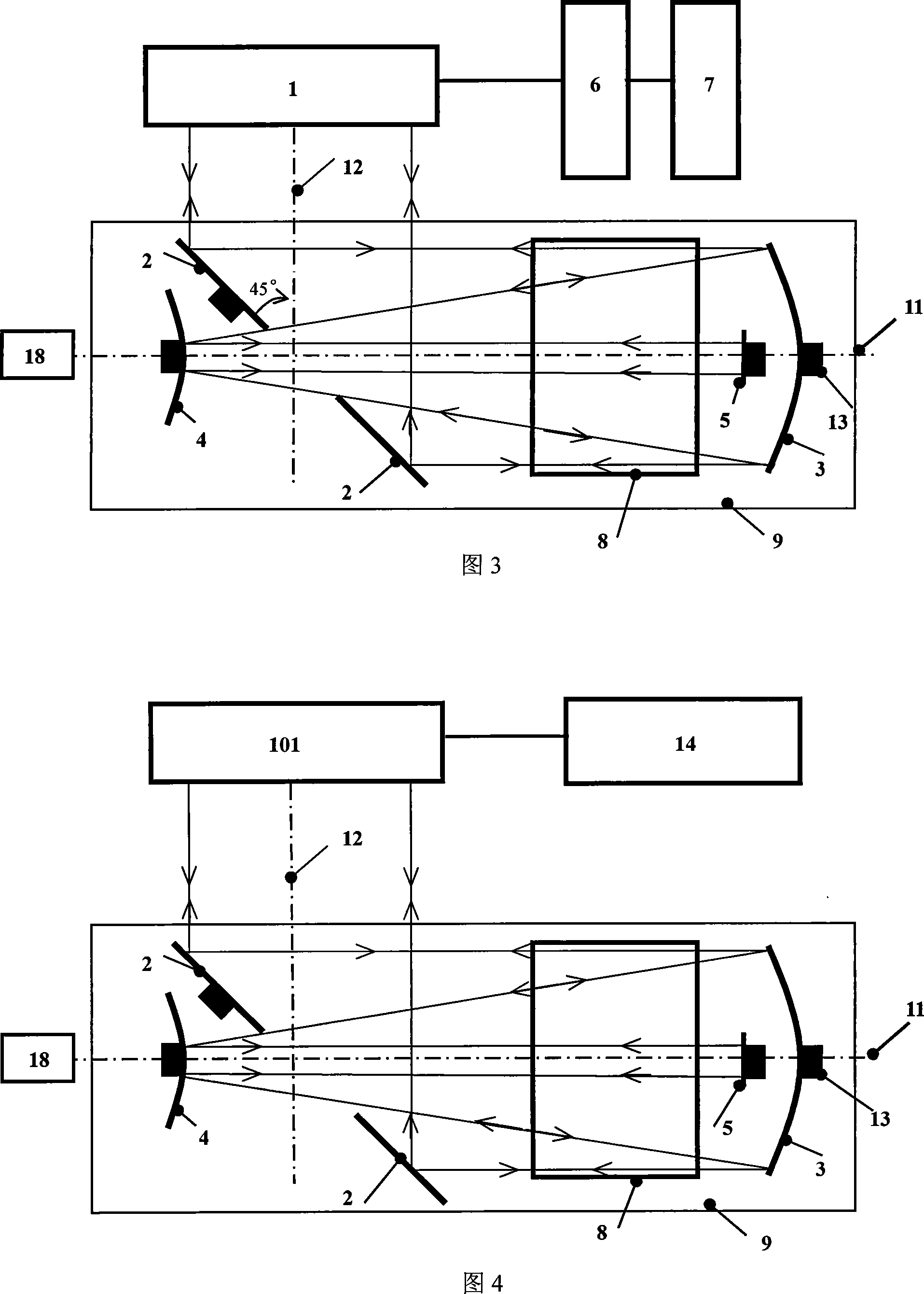
[0042] As shown in Figure 4, it is an embodiment of the present invention used in the positive branch confocal unstable cavity. As shown in this figure, the present invention uses the laser positive branch confocal unstable cavity automatic cavity adjustment system with the self-collimation feedback optical path, Its aberration detection system is a laser plane interferometer 101, and the output signal light is a beam of parallel light with a wavelength of 632.8nm. The data analysis system 6 and the cavity mirror control system 7 are realized by a computer 14 , that is, the system includes a laser plane interferometer 101 , an unstable cavity mirror, a feedback mirror 5 , a computer 14 and a laser base 9 . The unstable cavity mirror includes a second cavity mirror 4, an output coupling mirror 2 and a first cavity mirror 3, the first cavity mirror 3 is a concave mirror, the second cavity mirror 4 is a convex mirror, and the output coupling mirror 2 is placed in the first cavity ...

Embodiment 2

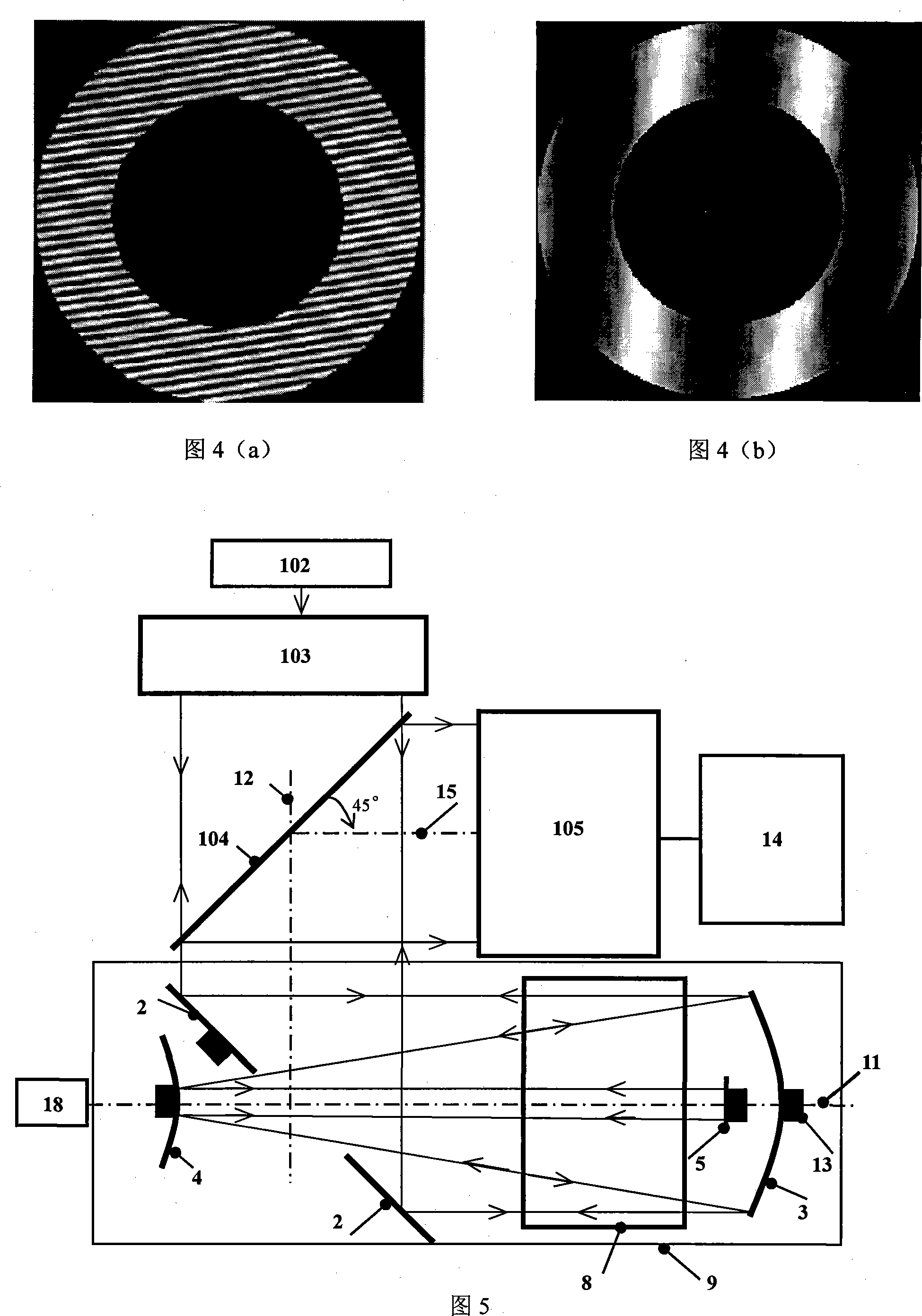
[0068] As shown in FIG. 5 , it is another embodiment of the present invention applied to the positive branch confocal unstable cavity. As shown in the figure, the present invention uses a laser positive branch confocal unstable cavity automatic cavity adjustment system with a self-collimation feedback optical path. The structure of the unstable cavity mirror is the same as that of Embodiment 1. An aberration detection system, the aberration detection system 1 is composed of a He-Ne laser 102 , a collimator 103 , a beam splitter 104 and a Hartmann wavefront sensor (or shearing interferometer) 105 . The optical axis 12 of the He-Ne laser 102 and the collimator 103 is perpendicular to the optical axis 11 of the unstable cavity. degree angle, the Hartmann wavefront sensor 105 is placed in the reflection path of the beam splitter and close to the beam splitter 104, its optical axis 15 is parallel to the optical axis 11 of the unstable cavity, and the Hartmann wavefront sensor 105 i...

Embodiment 3

[0077] As shown in FIG. 6 , it is an embodiment of the present invention applied to a negative branch confocal unstable cavity. As shown in the figure, the present invention uses a laser negative branch confocal unstable cavity automatic cavity adjustment system with a self-collimation feedback optical path. Its aberration detection system is a laser plane interferometer 101, and the output signal light is a beam of parallel light. The wavelength is 632.8nm. The data analysis system 6 and the cavity mirror control system 7 are implemented by a computer 14 , that is, the system includes a laser plane interferometer 101 , an unstable cavity mirror, a feedback mirror 5 , a computer 14 and a laser base 9 . The unstable cavity mirror includes a second cavity mirror 4, an output coupling mirror 2 and a first cavity mirror 3, the first cavity mirror 3 and the second cavity mirror 4 are concave mirrors, and the output coupling mirror 2 is placed on the second cavity mirror 4 Between ...


PUM


Abstract

The invention discloses an instable chamber automatic chamber adjusting system based on auto-collimating feedback optical path, and a relative adjusting method, for using an aberration detecting system, an instable chamber, and a feedback mirror to build an auto-collimating system for automatically adjusting instable chamber. The invention uses the aberration detecting system to obtain the optical aberration of reflected beam, according to Zernike aberration factors and system sensitivity matrix to calculate out the position bias of chamber mirror, thereby outputting a drive signal according to the position bias, to correct the position bias. The invention has the advantages that (1), the invention can detect the high-order aberration of chamber adjusting signal light, to make instable chamber adjustment more stable and accurate, (2), the invention can calculate the position bias of chamber mirror according to aberration directly, to adjust the instable chamber with fewer operation and high speed.

Description

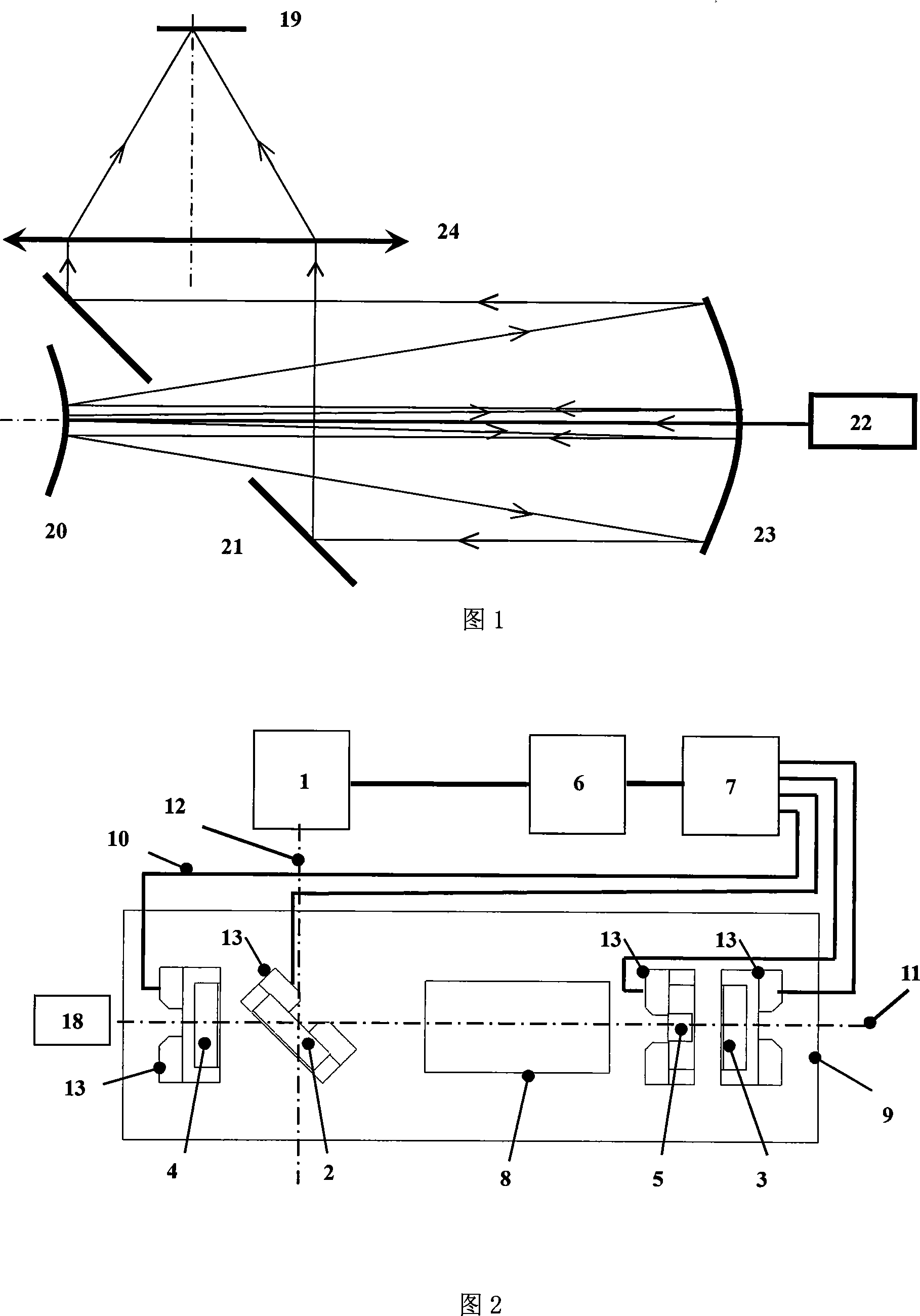
technical field [0001] The invention relates to the technical field of lasers, in particular to an unstable cavity automatic cavity adjustment system and a cavity adjustment method. Background technique [0002] The unstable cavity is the key device to realize laser energy extraction and output in high-energy lasers. Whether the collimation of the unstable cavity will directly affect the output beam quality and output power stability of the laser, so the laser must be checked during installation or operation. The adjustment of the resonant cavity mirror makes the position of the cavity mirror meet the design requirements to achieve the predetermined output index. [0003] At present, the cavity adjustment method of the unstable cavity of the high-energy laser generally adopts the Gaussian beam output by the He-Ne laser 22 as the guiding light (as shown in FIG. 1 ) and injects it into the unstable cavity through the small hole on the concave mirror 23, guiding In the resonan...

Claims


Application Information

Patent Timeline
IPC IPC(8): H01S3/086
Inventor 刘文广张文静刘泽金华卫红袁圣付李文煜
Owner NAT UNIV OF DEFENSE TECH
Learn More