Connector pin for printed circuit board

A technology for printed circuit boards and connectors, applied in the field of connectors for printed circuit boards, can solve the problems of copper foil pattern falling off or peeling, reducing welding effect, and excessive application, so as to reduce poor contact or poor action, and improve bonding. The effect of force, reinforcement welding state

Inactive Publication Date: 2008-01-02
DPC CO LTD
View PDF0 Cites 0 Cited by
  • Summary
  • Abstract
  • Description
  • Claims
  • Application Information

AI Technical Summary

Problems solved by technology

[0005] However, the above-mentioned fixing structure will exert too much force when bending various parts, which may cause the copper foil pattern on the printed circuit board to fall off or peel off, especially the aluminum coil with relatively weak ductility is particularly easy to be bent at the end of the bend. It is broken by bending force during the process, and the welding effect is reduced due to the difference in material properties and solder, and the coil covering layer needs to be removed when the printed circuit board is energized (usually coated with paint for insulation)

Method used


Image

  • Connector pin for printed circuit board
  • Connector pin for printed circuit board
  • Connector pin for printed circuit board

Examples


Embodiment Construction

[0019] The present invention will be described in detail below in conjunction with the accompanying drawings and embodiments. In the present invention, the content closely related to the gist of the present invention will be described emphatically, and the description of some known specific structures will be omitted.

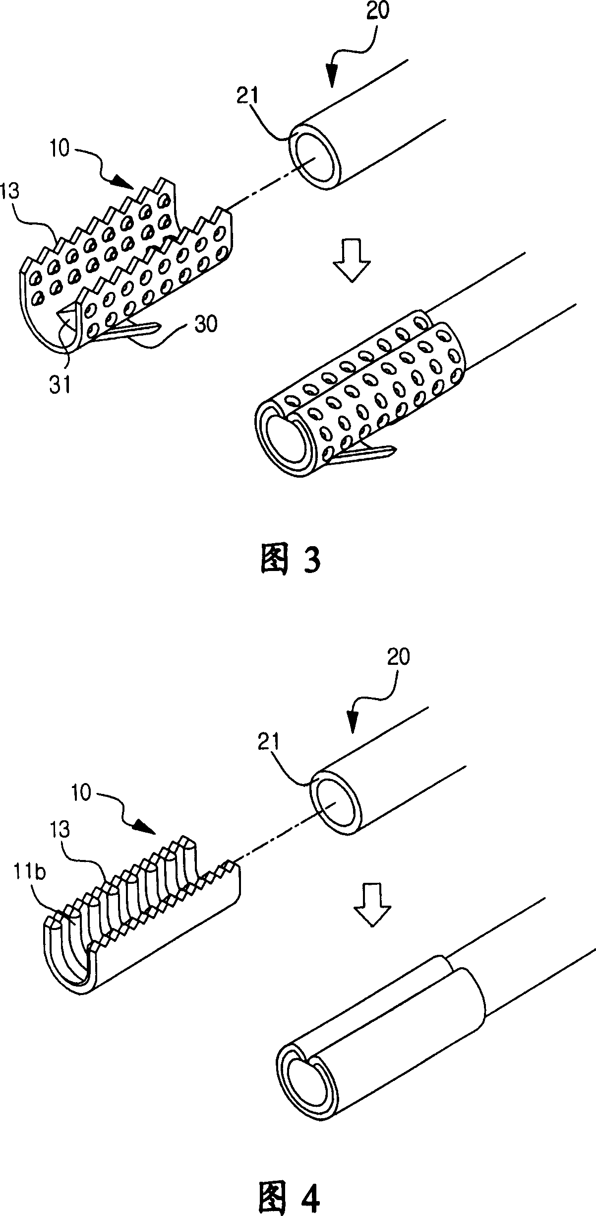
[0020] As shown in Figure 1, according to a connector for printed circuit boards according to an embodiment of the present invention, a plurality of cylindrical protrusions 11a are formed on the inner surface of the upper open semicircular connector 10, and through holes are processed at the tail ends of the protrusions 11a 12. Place the coil 20 on the inner surface of the connector 10, crimp both sides of the connector 10, and make the protrusion 11a cut through the covering layer 21 of the coil 20.

[0021] The shape of the connector 10 may be changed according to the shape of the coil or parts so that the target coil or various parts are located on the inner...


PUM


Abstract

The present invention discloses a connector of the printed circuit board, a projecting block is formed at the inner surface of the connector and the invention uses the single-press process that the coil covering layer is cut by the projecting block to insure the electric binding force, increase the operability and the productability, and firmly hold the soldering state. The connector of the printed circuit board of the invention is characterized in that a plurality of projecting blocks are formed at the inner surface of the top-open connector and a through hole is formed at the end of the projecting block, the coil is parked at the inner surface of the connector and the two sides of the connector is clamped thereby causing that the projecting block excides the coil covering layer.

Description

technical field [0001] The present invention relates to a connector pin for printed circuit board. The present invention forms protrusions on the inner surface of the connector, and ensures electrical bonding force through a crimping process of cutting the coil covering layer with the protrusions. Improve operability and productivity, and firmly maintain the welded state. Background technique [0002] In general, printed circuit boards (PCB: printed circuit board) use copper-clad laminates as their materials. Copper-clad laminates are formed by uniformly and firmly adhering micron-thick electrolytic copper foil to plastic laminates. Then print a Register with a specific circuit pattern on it, remove unnecessary copper foil by etching, and then dissolve the aforementioned Register with a solvent or alkaline liquid to obtain a printed circuit board with a specific pattern. [0003] In order to form a specific circuit on the above-mentioned printed circuit board, first install...

Claims


Application Information

Patent Timeline
Patent Type & Authority Applications(China)
IPC IPC(8): H01R12/22H01R13/62H01R12/71
CPCH05K3/34H05K5/0069H05K7/12
Inventor 金泰民卞长孝金大权
Owner DPC CO LTD
Why Eureka
Try Eureka