Roots blower
A Roots blower and labyrinth technology, applied in the direction of mechanical equipment, machines/engines, rotary piston machinery, etc., can solve the problems of poor sealing effect, difficulty in manufacturing and installation, poor sealing performance, etc., and meet the requirements of lower precision, installation And maintenance is convenient, the effect of reducing the sealing gap
- Summary
- Abstract
- Description
- Claims
- Application Information
AI Technical Summary
Problems solved by technology
Method used
Image


Examples
Embodiment 1
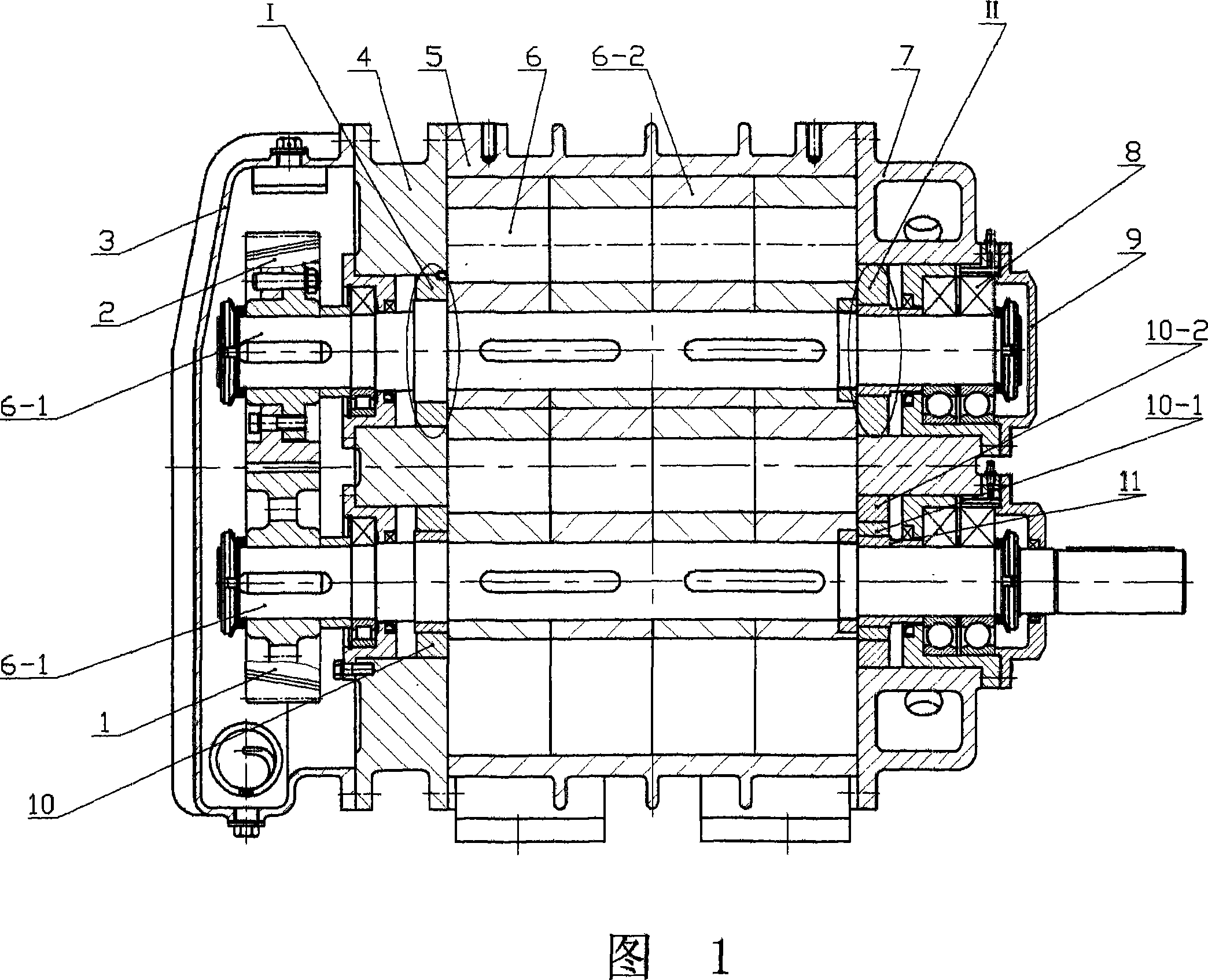
[0019] Referring to Fig. 1 and Fig. 2, a Roots blower includes a driving gear 1, a driven gear 2, a gearbox cover 3, a left wallboard 4, a casing 5, a rotor 6, a right wallboard 7, a bearing 8 and a bearing cover 9. The rotor 6 is composed of the impeller shaft 6-1 and the impeller 6-2. Fig. 2 is an enlarged view of part I of Fig. 1. In Fig. 2, the impeller shaft 6-1 has trapezoidal external teeth 12, and the left wallboard has 4 shaft holes There are rectangular internal teeth 13 on the labyrinth cover 10, and the labyrinth cover 10 is made of cast aluminum material. The trapezoidal external teeth 12 on the impeller shaft 6-1 and the rectangular internal teeth 13 on the labyrinth sleeve 10 all adopt ring-shaped teeth, and the number of teeth is 3 to 11 teeth. In the working state, at least three pairs of teeth at the tooth ends of the trapezoidal external teeth 12 and the rectangular internal teeth 13 are opposite to each other, and there is a small gap, which ensures that th...
Embodiment 2
[0022] Embodiment 2 is a modified example of Embodiment 1. Referring to Fig. 1 and Fig. 4, it can be seen that Fig. 4 is a modification example of part I in Fig. 1, that is, a modification example of Fig. 2 . Among Fig. 4, there is trapezoidal outer tooth 12 on the impeller shaft 6-1, and the labyrinth cover 10 in the 4 shaft holes of the left wallboard is formed by fastening the labyrinth outer cover 10-2 and the labyrinth inner cover 10-1. The outer labyrinth 10-2 is made of cast iron, and the inner labyrinth 10-1 is made of cast aluminum. The labyrinth inner sleeve 10-1 has rectangular inner teeth 13, the trapezoidal outer teeth 12 on the impeller shaft 6-1 and the rectangular inner teeth 13 on the labyrinth inner sleeve 10-1 are both annular teeth, and the number of teeth is 3~ 11 teeth. All the other structures are the same as in Embodiment 1.
Embodiment 3
[0024] Embodiment 3 is another transformation of Embodiment 1. Referring to FIG. 1 and FIG. 5 , it can be known that FIG. 5 is a modification example of part II in FIG. 1 , that is, a modification example of FIG. 3 . In Fig. 5, the impeller shaft 6-1 is fixedly sleeved with a labyrinth shaft sleeve 11, and the labyrinth shaft sleeve 11 has trapezoidal outer teeth 12, and a labyrinth sleeve 10 is housed in the 7 shaft holes of the right wallboard, and the labyrinth sleeve 10 is formed by a labyrinth jacket 10- 2 and the labyrinth inner sleeve 10-1 are fastened, and the labyrinth inner sleeve 10-1 has rectangular inner teeth 13. The outer labyrinth 10-1 is made of cast iron, and the inner labyrinth 10-1 is made of cast aluminum. Both the trapezoidal outer teeth 12 on the labyrinth shaft sleeve 11 and the rectangular inner teeth 13 on the inner labyrinth sleeve 10-1 are annular teeth, and the number of teeth is 3 to 11 teeth. All the other structures are the same as in Embodime...
PUM
 Abstract
Description
Claims
Application Information
 - R&D
- Intellectual Property
- Life Sciences
- Materials
- Tech Scout
- Unparalleled Data Quality
- Higher Quality Content
- 60% Fewer Hallucinations
Browse by: Latest US Patents, China's latest patents, Technical Efficacy Thesaurus, Application Domain, Technology Topic, Popular Technical Reports.
© 2025 PatSnap. All rights reserved.Legal|Privacy policy|Modern Slavery Act Transparency Statement|Sitemap|About US| Contact US: help@patsnap.com