
Accelerator with braking function

A technology of acceleration device and brake function, which is applied in the direction of foot-operated starting device, arrangement of power device control mechanism, vehicle components, etc.

Inactive Publication Date: 2007-12-19
蒋华东 +1
View PDF0 Cites 3 Cited by
  • Summary
  • Abstract
  • Description
  • Claims
  • Application Information

AI Technical Summary

Problems solved by technology

The installation of this device is also limited by the location, and the flow rate of the oil in the cylinder will not be too ideal. When braking, because the throttle line is not separated, the engine is still running at high speed.

Method used


Image

  • Accelerator with braking function
  • Accelerator with braking function
  • Accelerator with braking function

Examples


Embodiment Construction

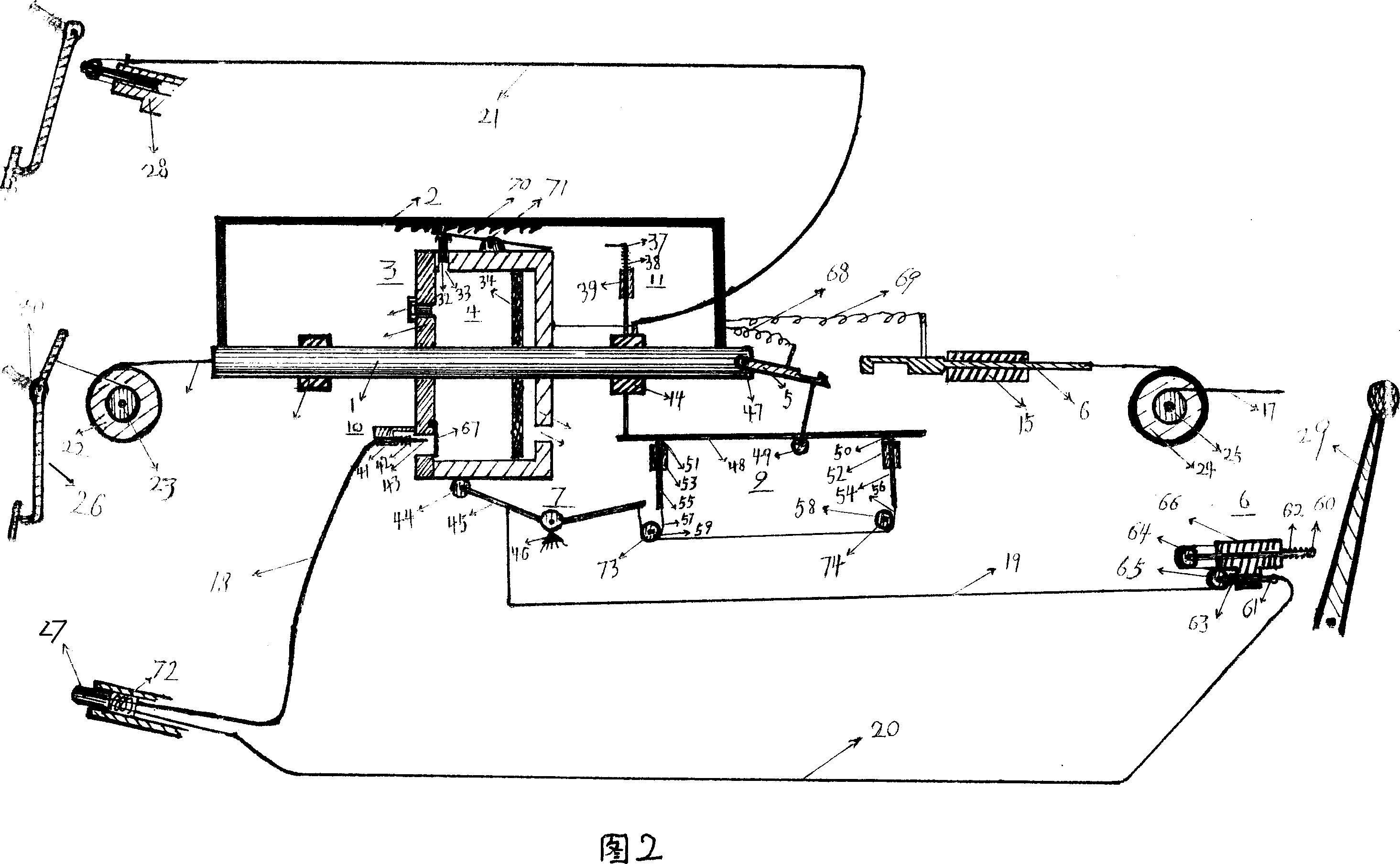
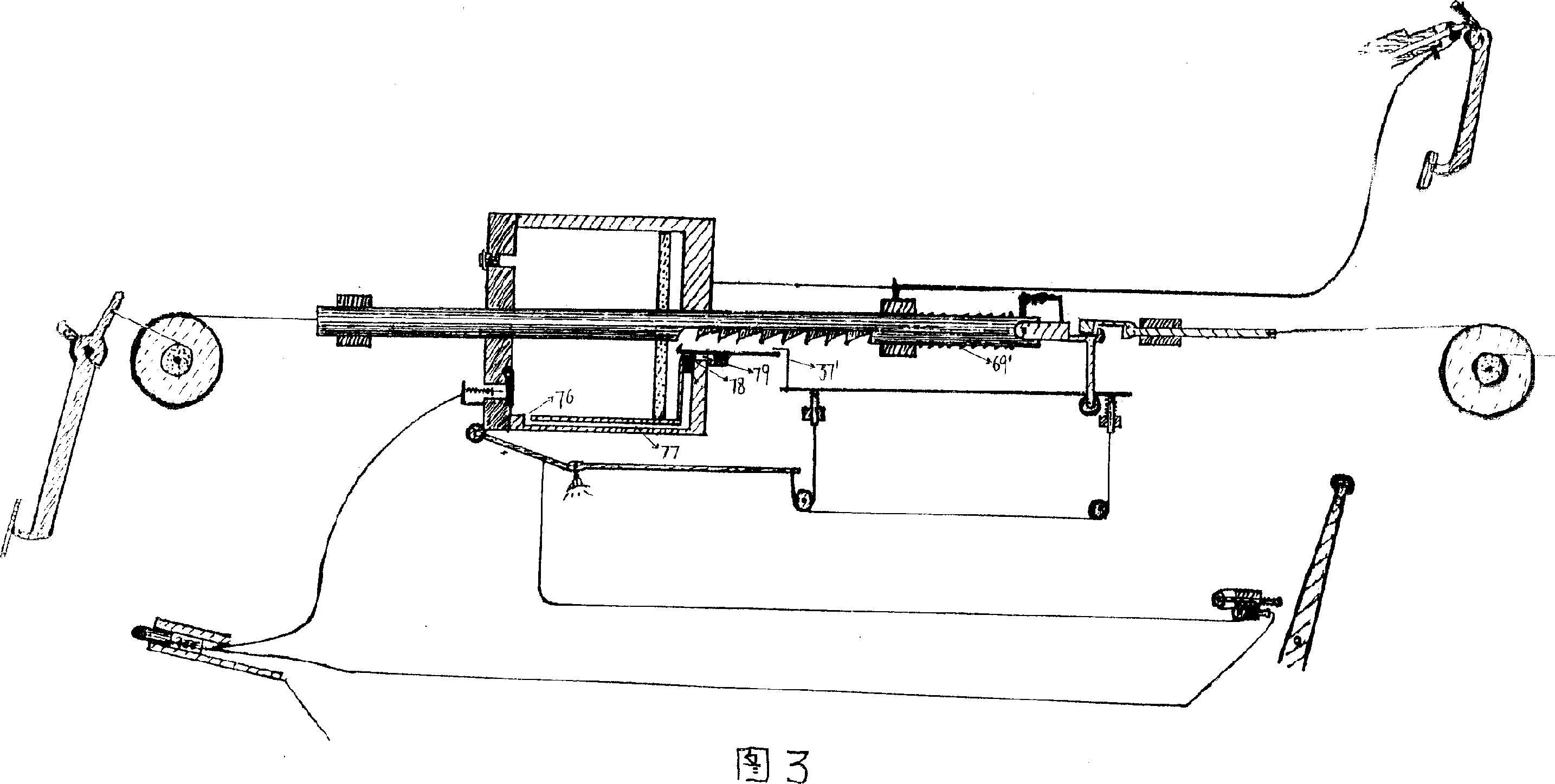
[0020] Fig. 1 and Fig. 2 have shown the first embodiment of the accelerator device with brake function of the present invention, and one end of pull rod 1 is connected with accelerator lever 26 through pull wire 16, and the other end is connected with a pull with return spring 68 flexibly. Hook piece 5 (will be described in detail below), pull rod is positioned by sliding seat 13,14, is fixed with a driven rod 2 that is processed with rack on the pull rod, and the axis of the cylinder 4 along it is swayed on the pull rod 1 On the pull rod, there is a cylinder device 3 that can slide (will be described in detail below), and there is a driven hook 6 that is connected to the throttle through a pull wire 17 and positioned by a sliding seat 15. There is a pull hook control device 8 (will be described in detail below), and what can transmit the sliding power of the cylinder 4 of the cylinder device 3 to the pull hook control device 8 is a transmission device 7 (will be described in d...


PUM


Abstract

The accelerator with braking function consists of an accelerating rod, an accelerating rod locating seat and its resetting spring, a pull wire and a conversion device. The conversion device includes a pull rod with one end connected through the pull with the accelerating rod and the other end connected to one pull hook with movable resetting spring and located by a sliding seat, a driven rod provided with gear rack and fixed onto the pull rod, a sliding cylinder unit, a driven hook, a pull hook controller, a driving unit to transfer the power of the cylinder unit to the pull hook controller, and a resetting spring for connecting the pull rod to the driven rod and the driven hook. The accelerator with braking function makes it possible that in case of error stepping on the accelerating rod, the vehicle is braked, rather than accelerated.

Description

technical field [0001] The invention relates to an acceleration device of a motor vehicle, in particular to an acceleration device with a braking function. Background technique [0002] So far, the acceleration device of a motor vehicle only has a single acceleration function. When stepping on it by mistake, it is easy to cause casualties and property losses. It is adopted and promoted by people, the reason is not ruled out, or because those ideas have greatly changed or affected the driver's usual operating habits, or the changes to the car are relatively large, or the sensitivity is not high, or the installation position is limited. Wait. [0003] Chinese Utility Model Publication No. 032012586 discloses a seesaw type automobile accelerator brake pedal for preventing stepping on the wrong accelerator, (announcement date is October 20, 2004). When flipping up and down on the seesaw pedal, either drive the accelerator control mechanism to act, or drive the brake mechanism ...

Claims


Application Information

Patent Timeline
Patent Type & Authority Applications(China)
IPC IPC(8): B60K26/02B60T7/06
Inventor 庄凌华
Owner 蒋华东
Learn More