High discharge capacity lithium battery
A battery and electrolyte technology, applied in the field of electrochemical batteries, can solve problems such as substrate deformation, material degradation, and failure
- Summary
- Abstract
- Description
- Claims
- Application Information
AI Technical Summary
Problems solved by technology
Method used
Image

Examples
Embodiment 1
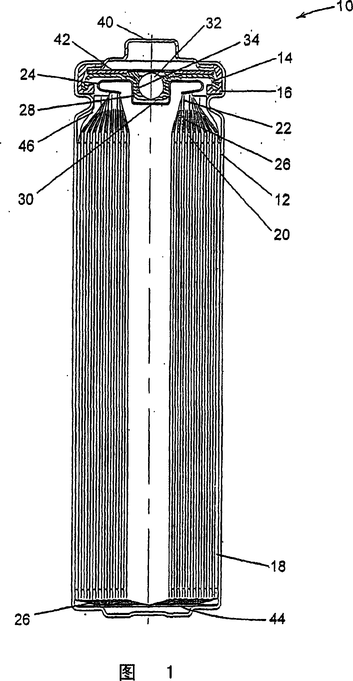
[0085] FR6-Type Cylindrical Li / FeS with Helically Wound Electrode Assembly 2 The battery is at about 0.373-about 0.455cm 3 The electrode assembly void volume per cm interface electrode assembly height in the range of 1 / cm was made. Void volume is varied by adjusting the volume of voids within the active material mixture coated on the cathode. This is accomplished through various combinations of mixture formulation, thickness and assembly. The separator material used in all cells was a highly crystalline, uniaxially oriented microporous polypropylene material with a nominal thickness of 25 μm.
Embodiment 2
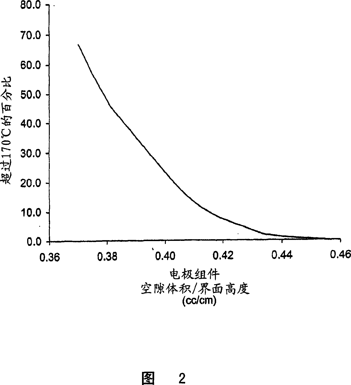
[0086] A sample of the battery of Example 1 was prepared for testing. For each group with a given void volume per unit height, some cells were left undischarged, while some cells were discharged 50% (at 200mA rate for the time required to remove 50% of the rated capacity). Tests related to the shock test were performed on undischarged and 50% discharged cells, monitoring the ambient temperature of each cell tested during the test and for 6 hours after the test.
[0087] For impact testing, the sample cell is placed on a flat surface, a 15.8 mm diameter rod is placed across the center of the sample, and a 9.1 kg object is dropped onto the sample from a height of 61 ± 2.5 cm. Sample cells were impacted with their longitudinal axis parallel to the flat surface and perpendicular to the longitudinal axis of a 15.8 mm diameter rod spanning the center of the cell. Each sample is subjected to only one impact.
[0088] The ambient temperature of the undischarged batteries did not exc...
Embodiment 3
[0091] Four batches of FR6 cells were manufactured, each batch having a separator made of a different material. A description of the separator materials is provided in Table 1 and typical separator properties, as determined by the method described below, are summarized in Table 2. The separator material used for Batch A was the same as that used for the cells in Example 1. Each cell contains about 1.60 g of electrolyte composed of 1,3-dioxolane, 1,2-dimethoxyethane and 3,5-dimethylisoxazole (63.05:27.63:0.18 , by weight) of 9.14 wt% LiI salt composition in the solvent blend.
Table 1
Batch A
Batch B
Batch C
[0092] For all batches A-D, the same cell design was used. This cell design is one that has a larger amount of active material, a higher concentration of FeS in the cathode mixture than the cell of Example 1 (with an electrode assembly void volume to interfacial height ratio of about 0.452) 2 And a design with a higher electrode interfacial surface ...
PUM
| Property | Measurement | Unit |
|---|---|---|
| particle size | aaaaa | aaaaa |
| particle size | aaaaa | aaaaa |
| particle size | aaaaa | aaaaa |
Abstract
Description
Claims
Application Information
 - R&D
- Intellectual Property
- Life Sciences
- Materials
- Tech Scout
- Unparalleled Data Quality
- Higher Quality Content
- 60% Fewer Hallucinations
Browse by: Latest US Patents, China's latest patents, Technical Efficacy Thesaurus, Application Domain, Technology Topic, Popular Technical Reports.
© 2025 PatSnap. All rights reserved.Legal|Privacy policy|Modern Slavery Act Transparency Statement|Sitemap|About US| Contact US: help@patsnap.com