
Method for measuring optical film absorption loss

An optical thin film and laser technology, which is applied in the direction of testing optical properties, measuring devices, and optical instrument testing, to achieve good stability, improve sensitivity, and reduce measurement errors.

Inactive Publication Date: 2007-12-05
INST OF OPTICS & ELECTRONICS - CHINESE ACAD OF SCI
View PDF0 Cites 24 Cited by
  • Summary
  • Abstract
  • Description
  • Claims
  • Application Information

AI Technical Summary

Problems solved by technology

[0004] The technology of the present invention solves the problem: overcomes the deficiencies of the existing thin-film optical element absorption loss testing technology, and provides a method for measuring the optical thin-film absorption loss, which can improve the time and time for measuring the optical thin-film absorption loss compared with the laser calorimetry technology. Spatial resolution, compared with photothermal deflection or thermal lens technology, reduces the complexity and difficulty of experimental optical path debugging, reduces measurement errors, and can measure thin-film optics of low thermal expansion coefficient substrate materials or low refractive index temperature coefficient substrate materials Absorption loss of components, and can be used to monitor real-time changes in absorption loss and optical performance stability of thin film components

Method used


Image

  • Method for measuring optical film absorption loss
  • Method for measuring optical film absorption loss

Examples


Embodiment Construction

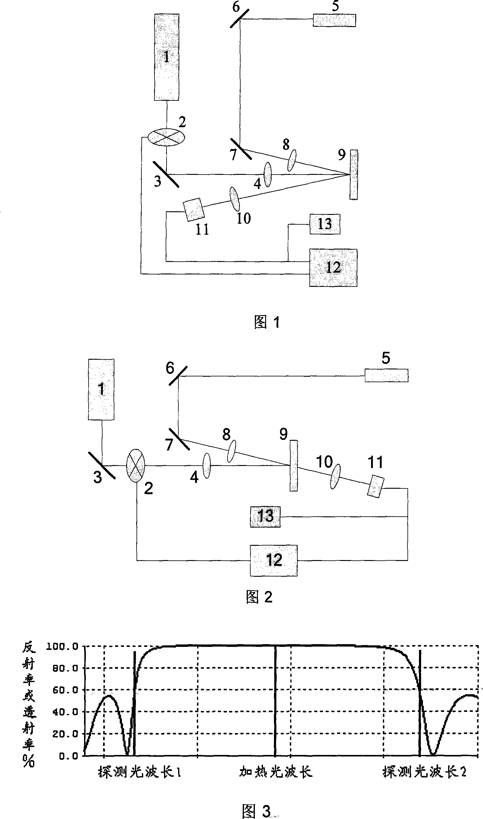
[0017] As shown in Figures 1 and 2, the measuring device for implementing the method of the present invention can be a reflective measuring device or a transmissive measuring device, consisting of a heating laser light source 1, a chopper or an acousto-optic modulator 2, a mirror 3, 6 and 7 , Lenses 4, 8 and 10, detection laser light source 5, optical film sample to be tested 9, detector 11, lock-in amplifier 12, and digital oscilloscope 13.

[0018] The specific implementation of the method of the present invention is as follows: the output beam of the heating laser light source 1 is intensity-modulated by an optical chopper or acousto-optic modulator or electro-optic modulator 2 (modulation frequency range 1Hz 1MHz, pulsed laser does not pass through the modulator) and then reflected The reflection of the mirror 3 changes the direction and the lens 4 focuses on the surface of the optical film element 9 under test, and the output signal of the chopper 2 is connected to the lock-i...


PUM


Abstract

A kind of method of measuring the optics thin film absorption loss and it is characterized in that: utilizes the drift phenomenon generating by the optics thin film component reflection or the transmitted spectrum changing with the temperature and collects the proper detection optical wavelength and adjusts the entrance angle of the detection laser-beam (low power) relative to the sample surface and makes the detection optical wavelength located in the maximum location of the brim of reflection or transmitted spectrum. Makes the strength cyclic modulate (high power) continuous or impulse leaser-beam as the heating light-struck thin film component thin layer and detecting the same or adjacent location and makes the detection light beam from the sample surface reflection or transmitted light strength modulated or generated the transient variation. Use the photoelectric detection to monitor the real-time variation of the detection light strength of the thin film component reflection or transmission of the illuminating process of heating leaser-beam and monitor the absorption loss water of the thin film and the real-time variation of the optics performance and it can realize the absolute measurement of actual absorption deterioration by scaling the signal amplitude of vibration. In addition that it can realize the two-dimension high resolution imaging of the absorption deterioration by scanning the lateral attitude of the thin film component. The method can enhance the sensitivity of measurement the absorption deterioration at some conditions.

Description

Technical field [0001] The invention relates to a method for measuring the parameters of an optical film element, in particular to a method for measuring the absorption loss of the optical film. Background technique [0002] Absorption loss is one of the important indicators to measure the performance of optical films. Especially in high-power laser applications, absorption loss not only causes thermal distortion of optical film components, reduces the beam quality of the laser beam, but also reduces the ability of the film to resist laser damage. , Limit the maximum power that can be output and transmitted in the laser and laser system. At the same time, accurate measurement of film absorption loss is also very important for optimizing film design and coating process to improve the performance of film components. Therefore, it is necessary to develop a highly sensitive test technique that can accurately measure the absorption loss of the optical film. [0003] The traditional sp...

Claims


Application Information

Patent Timeline
Patent Type & Authority Applications(China)
IPC IPC(8): G01M11/00G01M11/02
Inventor 李斌成郝宏刚
Owner INST OF OPTICS & ELECTRONICS - CHINESE ACAD OF SCI
Learn More