
Method for realizing numerical control rotating platform angular displacement forecast measurement using time gate displacement sensor

A technology of displacement sensor and time grating, which is applied in the direction of using electric/magnetic devices to transmit sensing components, digital control, electrical program control, etc., and can solve the problem that the time grating cannot be applied to dynamic continuous position feedback.

Inactive Publication Date: 2007-12-05
CHONGQING UNIV OF TECH
View PDF0 Cites 12 Cited by
  • Summary
  • Abstract
  • Description
  • Claims
  • Application Information

AI Technical Summary

Problems solved by technology

Therefore, current time gratings cannot be applied to dynamic continuous position feedback

Method used


Image

  • Method for realizing numerical control rotating platform angular displacement forecast measurement using time gate displacement sensor
  • Method for realizing numerical control rotating platform angular displacement forecast measurement using time gate displacement sensor
  • Method for realizing numerical control rotating platform angular displacement forecast measurement using time gate displacement sensor

Examples


Embodiment Construction

[0021] Below in conjunction with concrete hardware and software illustrate the realization of the inventive method:

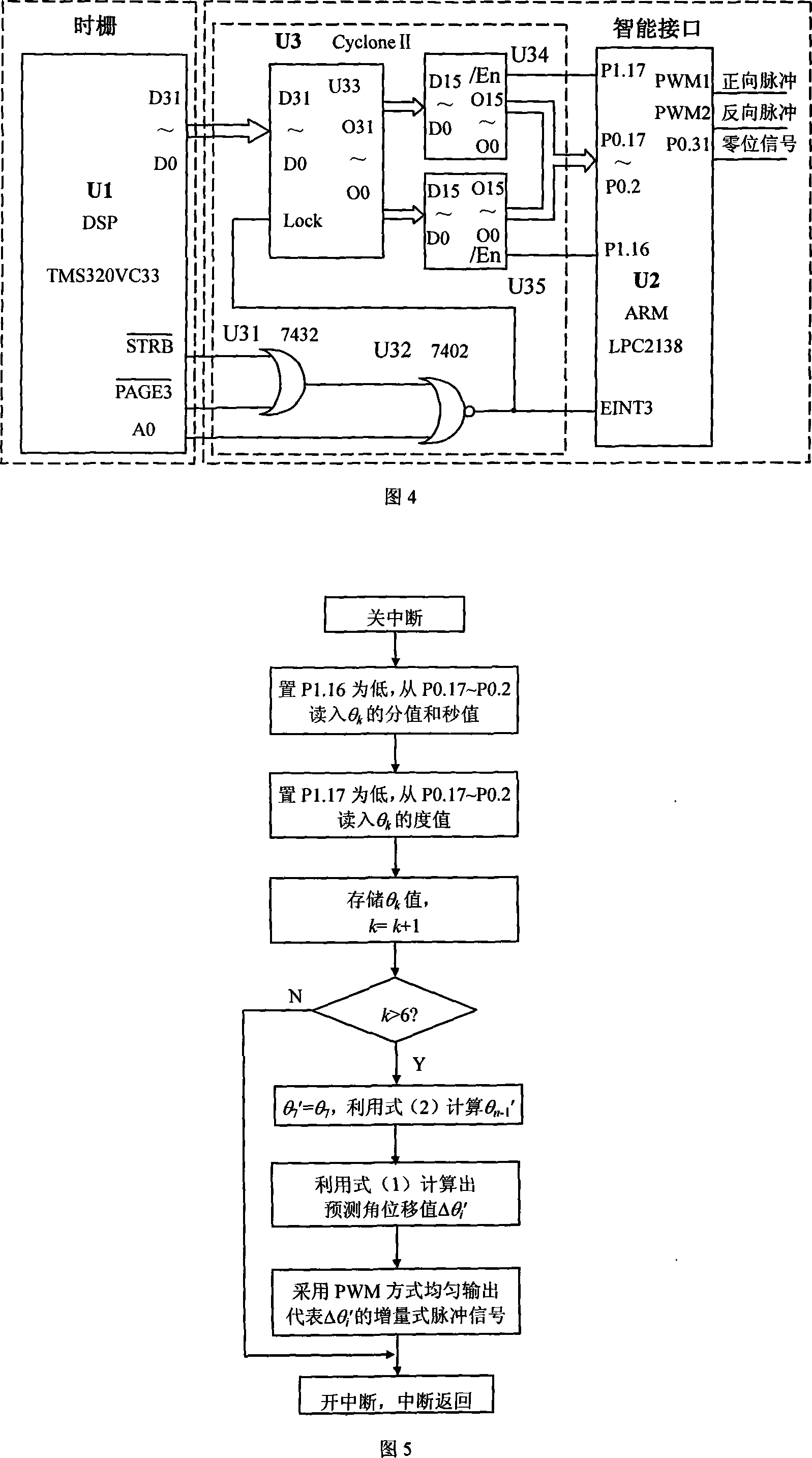
[0022] Referring to Figure 4, the time grid uses a digital signal processor DSP (U1) to process data, and its specific model is TMS320VC33. The / STRB and PAGE3 terminals of U1 pass through the OR gate U31, the output terminal of U31 is connected to one input terminal of the NOR gate U32, the other input terminal of U32 is connected to the AO terminal of U1, and the output terminal of U32 is connected to U1 in two ways The EINT3 end and the LOCK end of the latch U33. The 32 data input lines D31~D0 of U33 are connected with the 32 data lines D31~D0 of U1 in turn, and the 32 data output lines O31~O0 of U33 are respectively connected with two 16-bit tri-state bus buffers (U34 and U35). The data input lines D15-D0 are connected, and the data output lines O15-O0 of U34 and U35 are all connected to the P0.17-P0.2 terminals of the ARM processor LPC2138 (U2). The outp...


PUM


Abstract

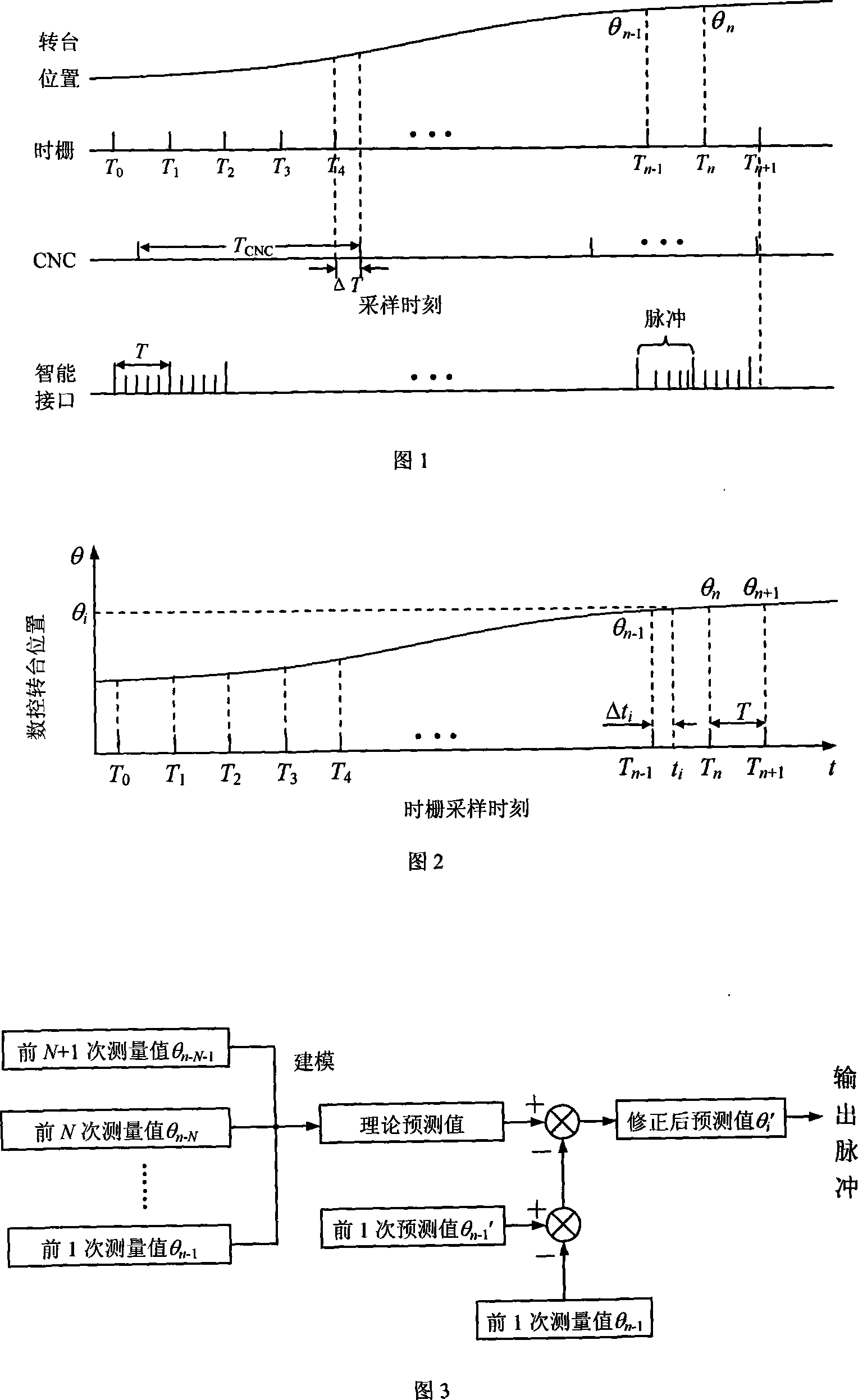
This invention provides a sort of metrical method which realizes the forecast of the angular displacement of the numerical control rotating floor by the time-bar displacement sensing device. Add an intelligent interface unit between the time-bar and the numerical control system, the import of the intelligent interface unit is the absolute value of the angle which is measured by the time-bar; the export is the increment type impulse signal which can connects with the currency numerical control system. The intelligent interface unit progresses the forecast to the angular displacement figures in the unborn spell according to several discrete absolute value of the measured angle of the time-bar which is in the nonce and in the past. It corrects the predictive error figures which are in the former time slice according to the real measured angle figures which is in now. It realizes the predictive measure of the angular displacement of the numerical control rotating floor. This invention applies to the displacement sensing device with the timing sampling that the time-bar is used to be the deputation, and it applies to the position feedback of the whole closed loop which is from the function unit of the numerical control division likes the numerical control rotating floor, and so on.

Description

technical field [0001] The invention relates to a new method for prediction and measurement of a displacement sensor. A timed sampling displacement sensor represented by a time grating can be used for full-closed-loop position feedback of numerical control indexing functional components such as a numerical control turntable. Background technique [0002] The time grid sensor is a newly invented displacement sensor, which uses time to measure the spatial position, and is a static absolute measurement sensor. The time grating designed based on the principle of static measurement, due to the existence of the measurement period (that is, the sampling period), there will be a measurement blind area within a certain period of time, and no new measurement results will be output. However, when the CNC system performs full-closed-loop servo control, it uses hardware timing interrupts to sample position feedback information. The timing period of the time grid and the CNC system are in...

Claims


Application Information

Patent Timeline
IPC IPC(8): G01D5/244G05B19/19
Inventor 彭东林刘小康费业泰万文略
Owner CHONGQING UNIV OF TECH
Learn More