Entry conveyor and pan section for the same

A technology for chute joints and conveyors, which is applied in the field of tunnel conveyors and chute joints for tunnel conveyors, which can solve the problems of high chain load, high proportion of scraper chain wear, high chain force, etc., and achieve wear reduction Effect

Active Publication Date: 2013-02-13
CATERPILLAR INC
View PDF0 Cites 0 Cited by
  • Summary
  • Abstract
  • Description
  • Claims
  • Application Information

AI Technical Summary

Problems solved by technology

In face-gate conveyors, despite the short construction length compared to the face conveyor, high chain forces and high chain loads High percentage of plate chain wear

Method used


Image

  • Entry conveyor and pan section for the same
  • Entry conveyor and pan section for the same
  • Entry conveyor and pan section for the same

Examples


Embodiment Construction

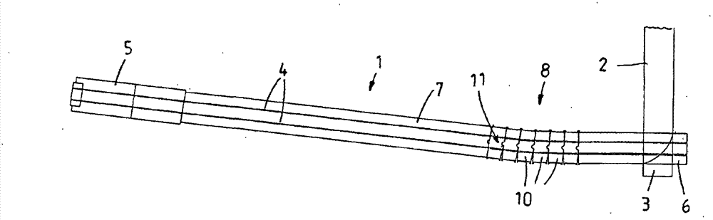
[0027] in figure 1 A roadway conveyor 1 which is constituted as a working face-levelway transfer conveyor is described in a schematic and simplified manner. For example, it can be used in underground mining, especially in coal mining. The material recovered by the face conveyor on a mining face not shown otherwise is thrown on a special trough formed as a cross frame (Kreuzrahmen) 3 onto the road conveyor 1, not only the face conveyor 2 here. In addition, the lane conveyors 1 are all configured as double middle scraper chain conveyors, including two chain strands 4 of a double middle scraper chain that are only schematically described here for the lane conveyor 1. The two shown chain strands 4 of the scraper chain run in the upper branch of the conveying trough 7 from the cross frame towards the drive station 5, which is composed of a number of standard chute sections that are identical to each other and are not shown in detail. This is known to the skilled person. The two cha...


PUM


Abstract

An entry conveyor including a conveyor pan formed by a plurality of pan sections that are hingeably connected to each other, at the two ends of which conveyor pan drive stations and / or return stations for a scraper chain are provided. Each pan section includes a top strand delimited by lateral profiles and the conveyor base and a bottom strand for the scraper chain as well as receiving elements for a pan section connecting mechanism, which elements are disposed outside of the lateral profiles. A pan strand including a plurality of pan sections that are disposed behind each other is provided in the conveyor pan, which sections are hingeably coupled via a center swivel bearing disposed on the center longitudinal axis of the conveyor pan or the pan sections. The invention also relates to the pan sections with the center swivel bearings.

Description

Technical field [0001] The invention relates to a roadway conveyor, in particular a roadway transfer conveyor or a crushing conveyor, comprising a conveying trough constituted by a plurality of chute sections connected to each other by means of a plurality of tensile ground and articulated movable ground (gelenkbeweglich). The two ends of the conveying trough are provided with driving stations and / or steering stations for the double scraper chain. Each chute section has an upper branch defined by the side profile and the conveying bottom and a lower branch for the scraper chain. An accommodating mechanism for the chute section connecting mechanism is arranged outside the side profile. The present invention also relates to a chute section for a corresponding leveling conveyor, comprising an upper branch defined by the side profile and the conveying bottom, a lower branch formed below the upper branch, and a chute section on the outer side of the side profile The accommodating me...

Claims


Application Information

Patent Timeline
Patent Type & Authority Patents(China)
IPC IPC(8): B65G19/28E21F13/02
CPCE21F13/06E21C35/20B65G19/28B65G19/287E21F13/00E21F13/066E21F13/08E21F13/083
Inventor S·施密特G·默滕H·梅亚J·维尔茨I·普鲁斯卡尔-海因茨·许雷尔R·布吕格曼
Owner CATERPILLAR INC
Why Eureka
Try Eureka