Wooden screw nail structure

A screw and thread technology, applied in the field of wood screw structure, can solve problems such as construction failure, jamming, waste, etc., and achieve the effect of eliminating labor-consuming force, labor-saving cutting operation, and enhancing the function of chip collection

Inactive Publication Date: 2007-11-28
徐国泰
View PDF0 Cites 1 Cited by
  • Summary
  • Abstract
  • Description
  • Claims
  • Application Information

AI Technical Summary

Problems solved by technology

[0003] However, the inventor of the present invention still feels that there should be room for improvement in the "improved structure of screws" and "improved structure of cutting threads of wood screws" in the above two cases; for example, No. 301373 "Improved structure of screws" The new patent case, although the tip of the nail is provided with cutting grooves and a number of obliquely parallel spiral cutting patterns are set between the spirals, the whole can achieve favorable positioning of the digging hole and can be uniformly crushed to facilitate chip removal and avoid wood cracks However, when the screw is first screwed into the wood, it is hindered by the hardness of the wood structure, it has no auxiliary drilling and cutting functions, and the cutting strength is still not large enough, and the large amount of wood chips when the screw is first screwed has not yet reached the optimum concentration. The situation of chipping may cause jamming and twisting, and the construction may not be smooth. The whole operation still needs to consume a lot of force, and consumers also feel the lack of difficulty in screwing in; another example, No. 512897 "wooden New patents such as "Screw Cutting Thread Structure Improvement", although the thread at the screw-in end has cutting teeth to assist the cutting function, it is still lacking in chip removal and chip collection, and the straight section is on the screw. Between the middle section and the rear section of the wood, because the sawdust cannot be discharged, it is pushed outwards from the straight section to the surrounding tissue of the object, so that the object swells outward, and even seriously damages the appearance of the object.
[0004] Therefore, in view of the above-mentioned two new patents, the present inventor still has the problem of not being able to perform multiple functions such as auxiliary cutting, chip removal and better chip collection during the screw fixing process, resulting in an unsatisfactory problem. Therefore, adhering to many years of professional experience in this technical field, in order to strive for the concept of product excellence, especially to improve and innovate the inadequacies of the above-mentioned screws, we finally successfully developed a screw that can actually lock the screw at the same time. , due to the design of its structure with the functions of fast cutting, chip removal and chip collection, it achieves the utilization value of this industry

Method used


Image

  • Wooden screw nail structure
  • Wooden screw nail structure
  • Wooden screw nail structure

Examples


Embodiment Construction

[0021] Specific embodiments of the present invention are described below in conjunction with accompanying drawing:

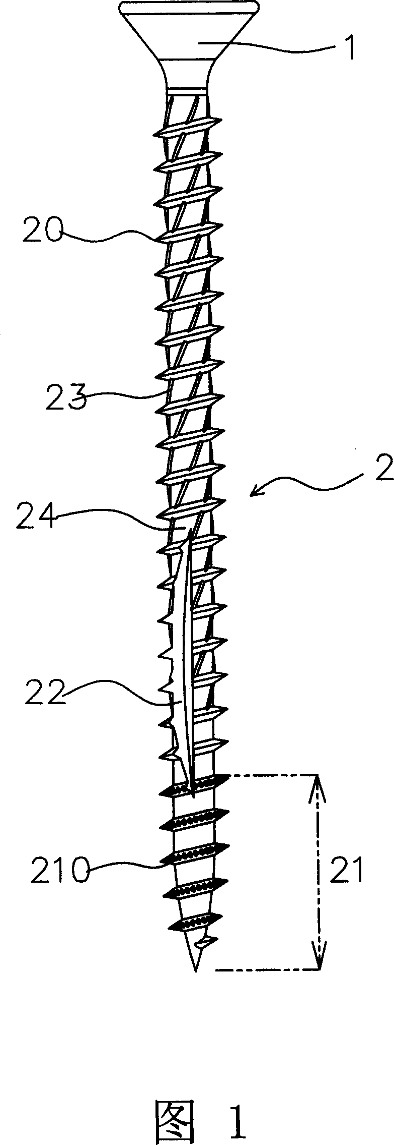
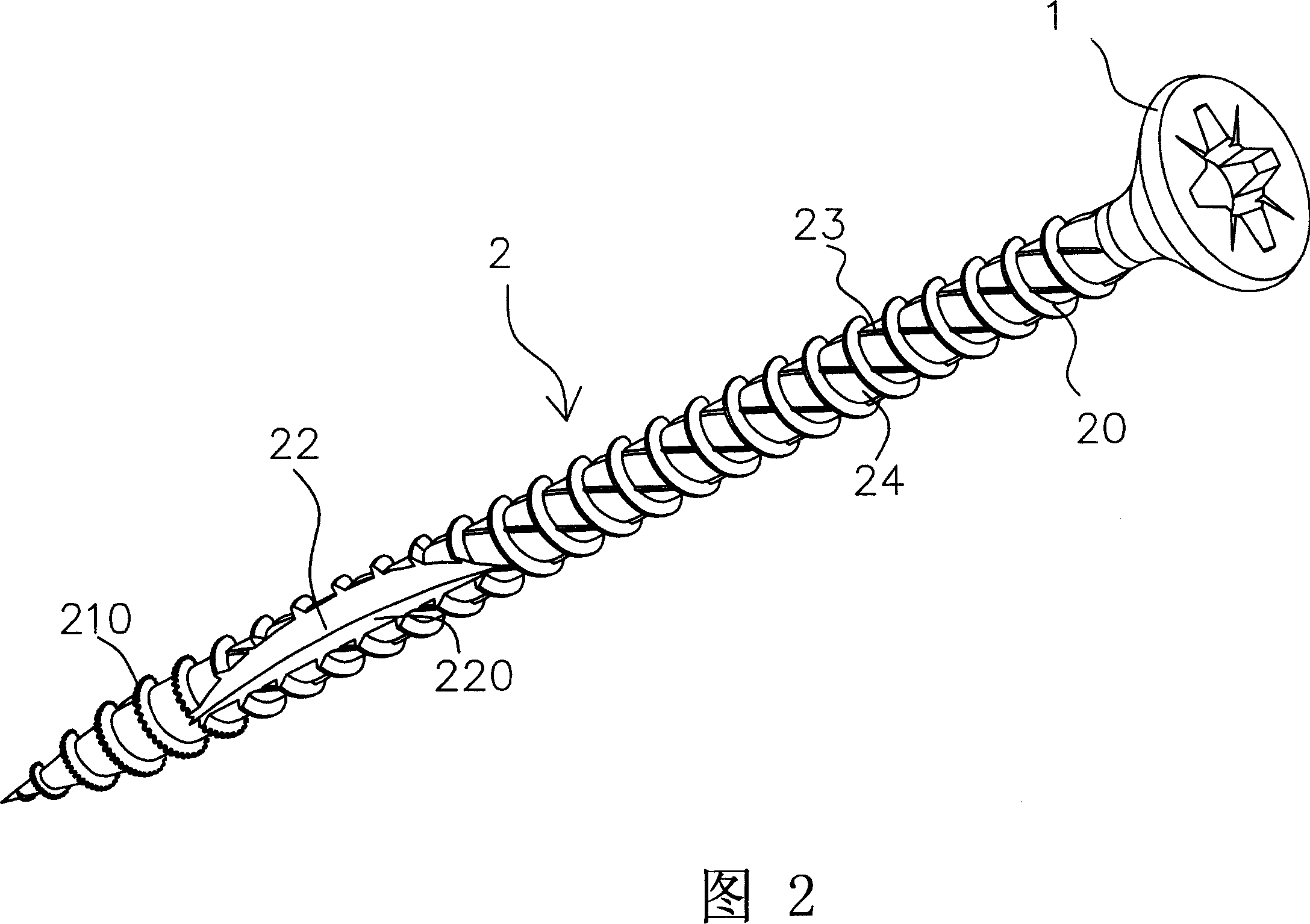
[0022] Referring to Fig. 1 and Fig. 2, the wood screw of the present invention is mainly composed of a head 1, a shank 2 and a plurality of threads 20 formed on the shank 2 and extending axially, wherein:

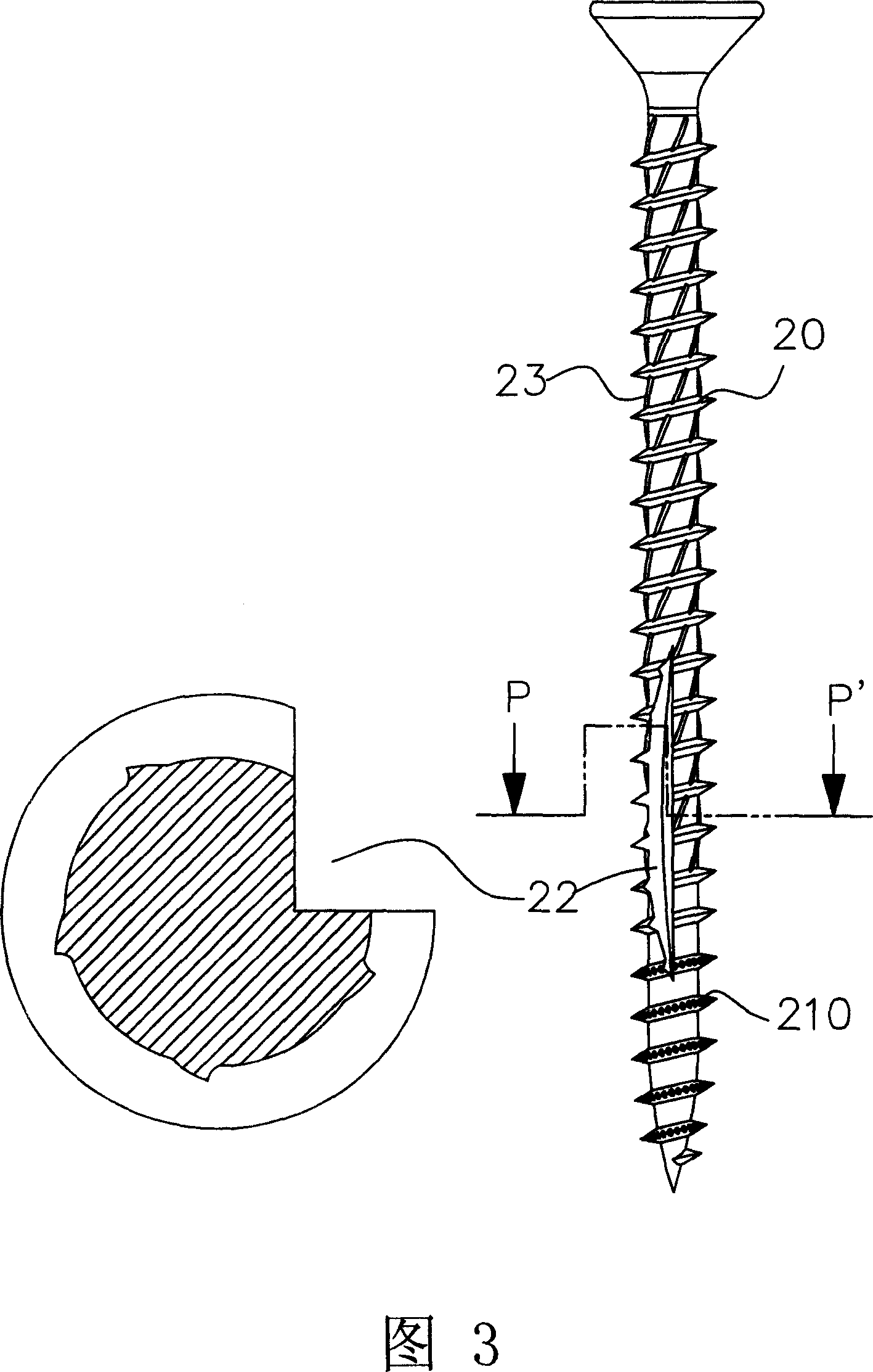
[0023] The rod part 2 is provided with a screw-in end 21 at the tip, and a plurality of cutting teeth 210 are provided on the plurality of threads 20 of the screw-in end 21, and a chip collecting groove 22 is longitudinally excavated behind the cutting teeth 210, and the chip collecting A cutting surface 220 is formed on both sides of the groove 22 , and the cutting teeth 210 extend backward to between the plurality of threads 20 of the head 1 , and are surrounded by protruding ribs 23 arranged obliquely.

[0024] Please refer to Fig. 3 and shown in Fig. 4, when the wood screw of the present invention is used and implemented, the work system in the initial st...


PUM


Abstract

The invention discloses a wood screw structure. The wood screw comprises head part, bar part and plural screw thread formed on the bar part and extending along the axial direction. Thereinto, multiple cutting teeth are set on the screw thread of screw-in end of bar part and cutting teeth extend backward to the tooth bottom of head part among plural screw thread. Convex ribs arranged obliquely are set in circle. Chip collecting groove is dug in vertical direction after cutting teeth of the screw-in end and a cutting face is formed at two sides of groove. The cutting face collects sawdust of screw-in end and carries discharging efficiency of back segment of bar part. Because of design mentioned above, the screw is provided with cutting in saving labor, collecting chip and discharging chip quickly so on.

Description

technical field [0001] The invention relates to a wood screw structure, in particular to a wood screw structure with multiple functions to achieve labor-saving cutting, optimal chip collection, fast chip removal and enhanced screw fastening. Background technique [0002] Nowadays, DIY products are very popular and more and more buildings use wooden structures in large quantities. Wood screws have become simple and effective connectors. In addition to furniture and decoration, they are also widely used in architectural structures. However, for its structural design, it not only requires simple locking, but also pays more attention to the work efficiency in the locking process. Therefore, the inventor has made several constructive improvements. Chinese Taiwan Patent Announcement No. 301373 "Screw Improved Structure” and Announcement No. 512897 “Improved Cutting Thread Structure of Wood Screws” and other new patent cases, it can be clearly seen that these two cases not only ful...

Claims


Application Information

Patent Timeline
IPC IPC(8): F16B25/04
Inventor 徐国泰
Owner 徐国泰
Why Eureka
Try Eureka