
System and method for beam expansion with near focus in display device

A focal length and equipment technology, applied in the direction of light guides, instruments, light guides, etc. of the lighting system, can solve the problems of reducing the ergonomics of the display, achieve comfortable viewing images, and improve ergonomics

Active Publication Date: 2007-11-21
MAGIC LEAP INC
View PDF1 Cites 6 Cited by
  • Summary
  • Abstract
  • Description
  • Claims
  • Application Information

AI Technical Summary

Problems solved by technology

The disadvantage is that it reduces the ergonomics of the display, since for some applications it is more comfortable for the viewer to view the image at a distance shorter than infinity

Method used


Image

  • System and method for beam expansion with near focus in display device
  • System and method for beam expansion with near focus in display device
  • System and method for beam expansion with near focus in display device

Examples


Embodiment Construction

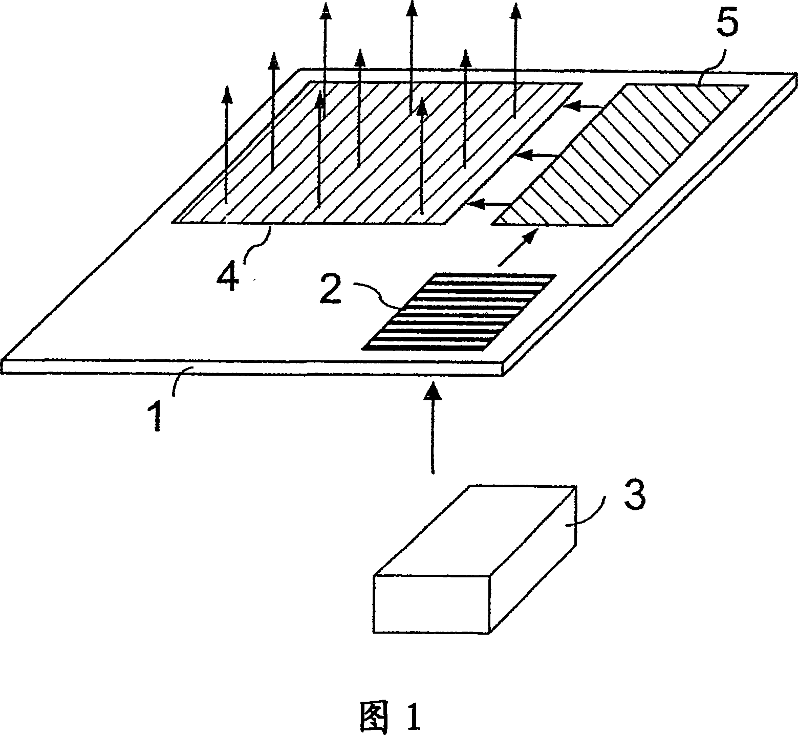
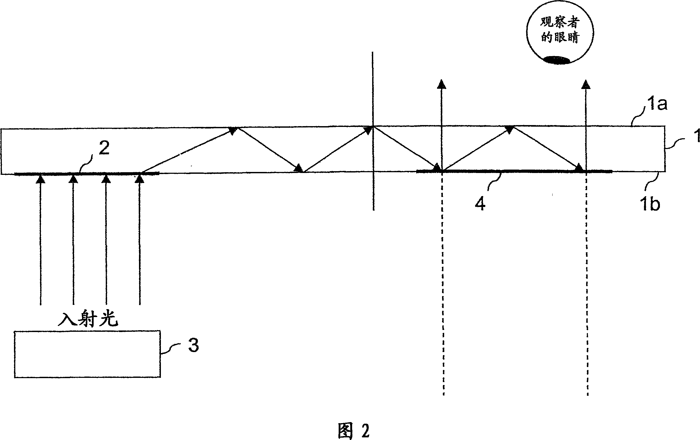
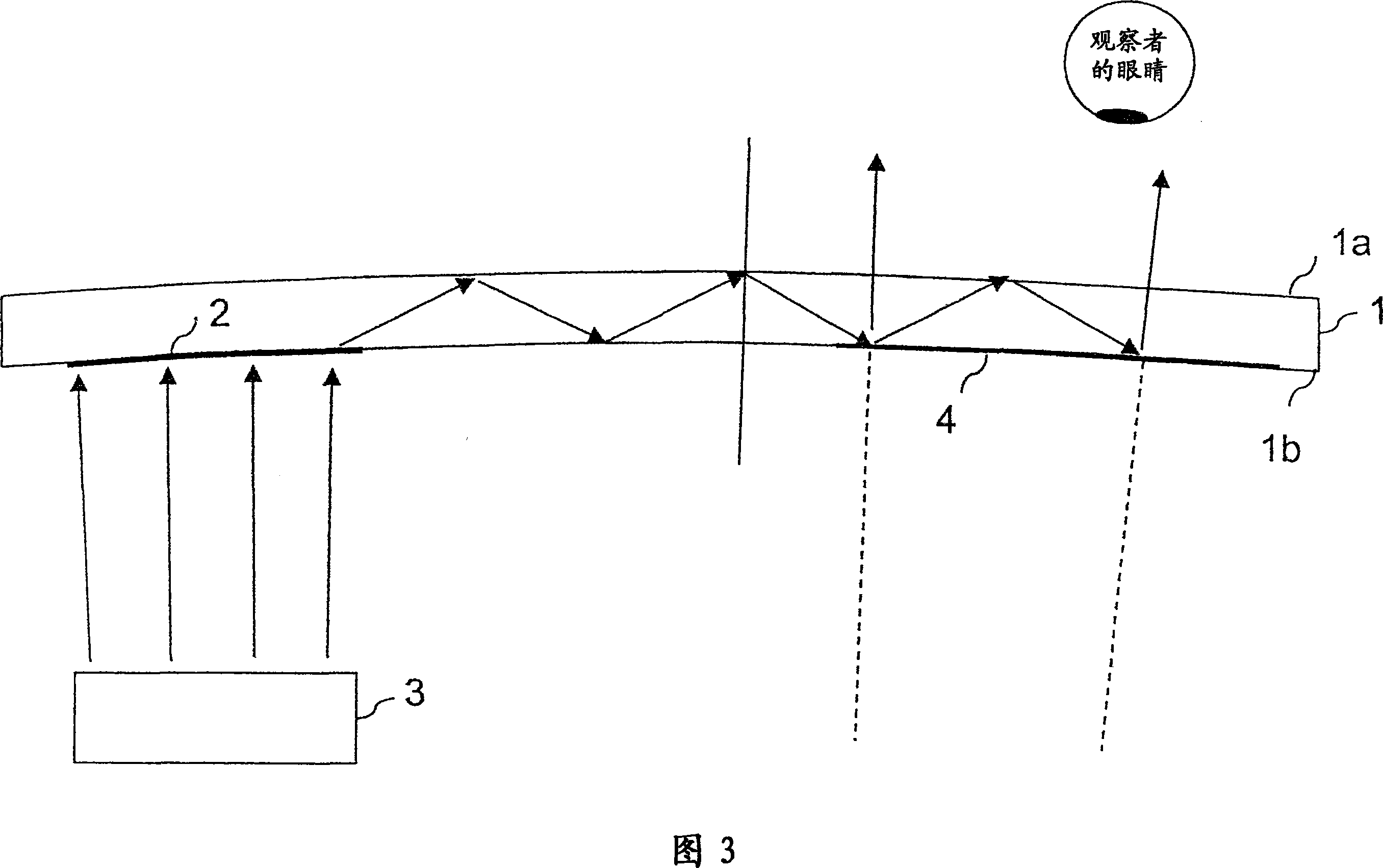
[0040] As shown in Fig. 3, the light guiding structure 1 has two opposing main surfaces 1a, 1b. In essence, these main surfaces 1a, 1b run parallel to the main plane of the structure 1 .

[0041] On the main surface 1 b side thereof, a first light coupling element 2 for coupling in light waves entering from an image source 3 is arranged.

[0042]It should be noted that each of diffractive element 2 and diffractive element 4 may be a holographic diffractive element (HOE) or a diffractive optical element (DOE). As its name suggests, holographic diffractive elements are fabricated holographically in which at least two coherent beams of light are used to create interference fringes. In contrast, diffractive optical elements can be manufactured mechanically or chemically. An EPE as shown in Figure 3 may have two or more diffractive elements.

[0043] Both types of elements are based on periodic structures, while DOE structures are generally simpler and usually surface relief str...


PUM


Abstract

A system and method are provided for processing audio and speech signals using a pitch and voicing dependent spectral estimation algorithm (voicing algorithm) to accurately represent voiced speech, unvoiced speech, and mixed speech in the presence of background noise, and background noise with a single model. The present invention also modifies the synthesis model based on an estimate of the current input signal to improve the perceptual quality of the speech and background noise under a variety of input conditions. The present invention also improves the voicing dependent spectral estimation algorithm robustness by introducing the use of a Multi-Layer Neural Network in the estimation process. The voicing dependent spectral estimation algorithm provides an accurate and robust estimate of the voicing probability under a variety of background noise conditions. This is essential to providing high quality intelligible speech in the presence of background noise.

Description

technical field [0001] The present invention relates generally to a display device for use in an electronic device, preferably a portable communication device, and more particularly to a display device using one or more optical coupling elements for extending the exit pupil of the display device (exit pupil) for viewing. Background technique [0002] While it has become common practice to use low resolution liquid crystal display (LCD) panels to display information, especially images and text messages in portable devices, it is preferable to use high resolution displays to view text and image rich information content. So-called microdisplay-based systems can provide full-color pixels at 50-100 lines per millimeter. Such a height resolution is generally suitable for virtual displays. A virtual display typically includes a microdisplay to provide an image and an optical configuration for manipulating the light emitted by the image so that it appears as large as looking direc...

Claims


Application Information

Patent Timeline
Patent Type & Authority Applications(China)
IPC IPC(8): G02B5/32G02B6/00
CPCG02B6/0033G02B6/0016G02B27/0081G02B5/32G02B27/0103G02B6/00
Inventor T·勒沃拉P·拉科南
Owner MAGIC LEAP INC
Learn More