
Device with vibration-damped component used for cutting and grinding, clamp device and rotary tool

A technology of clamping device and rotating tool, which can be applied to the cutting tool of the sawing machine device, the part of the grinding machine tool, the device of fixing the grinding wheel, etc., which can solve the problems of health damage and so on.

Inactive Publication Date: 2007-11-21
RHODIUS SCHLEIFWERKZEUGE
View PDF4 Cites 11 Cited by
  • Summary
  • Abstract
  • Description
  • Claims
  • Application Information

AI Technical Summary

Problems solved by technology

Therefore, in the case of operating the universal angle grinder for a long time, it will cause damage to health such as numbness of the forearm

Method used


Image

  • Device with vibration-damped component used for cutting and grinding, clamp device and rotary tool
  • Device with vibration-damped component used for cutting and grinding, clamp device and rotary tool
  • Device with vibration-damped component used for cutting and grinding, clamp device and rotary tool

Examples


Embodiment Construction

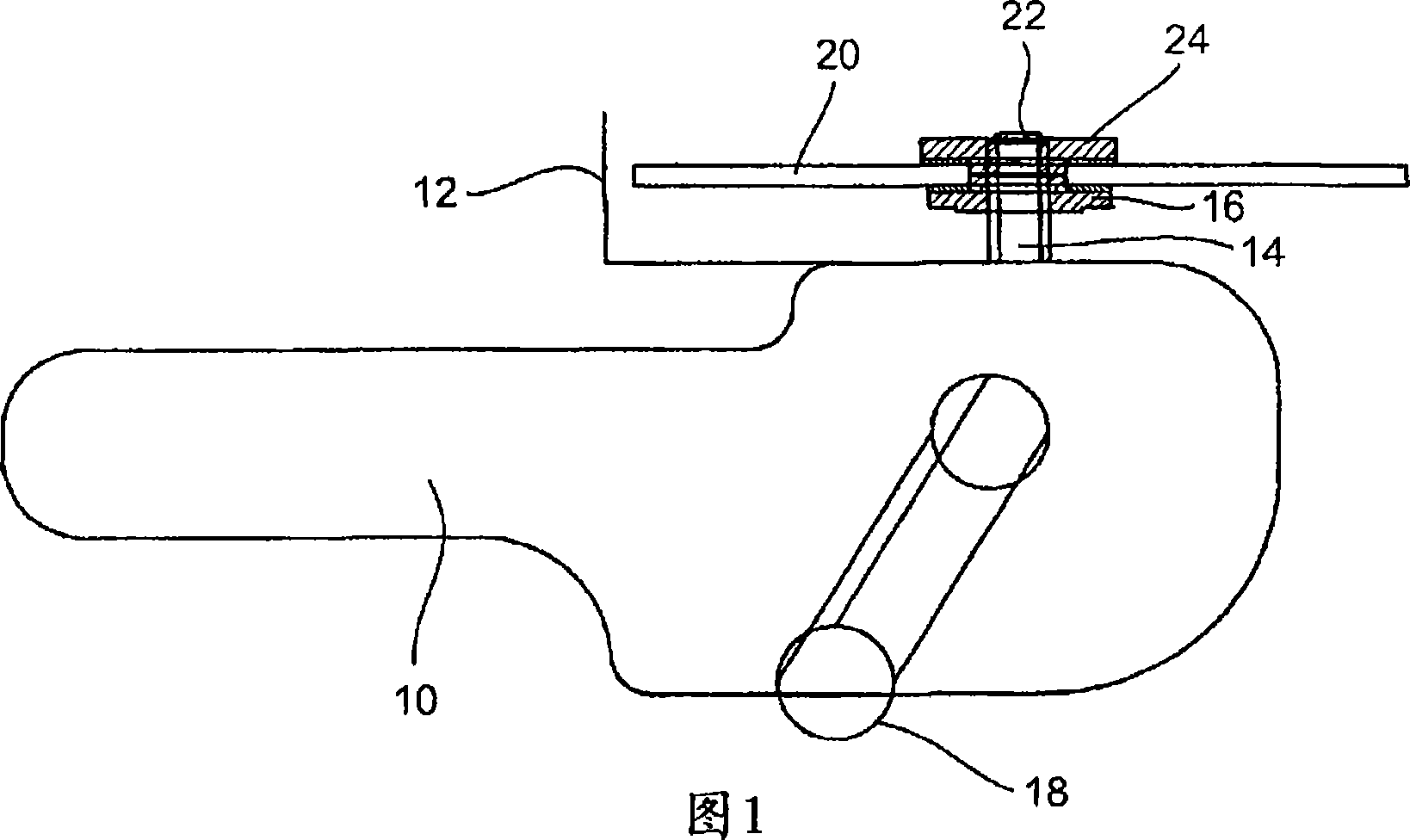
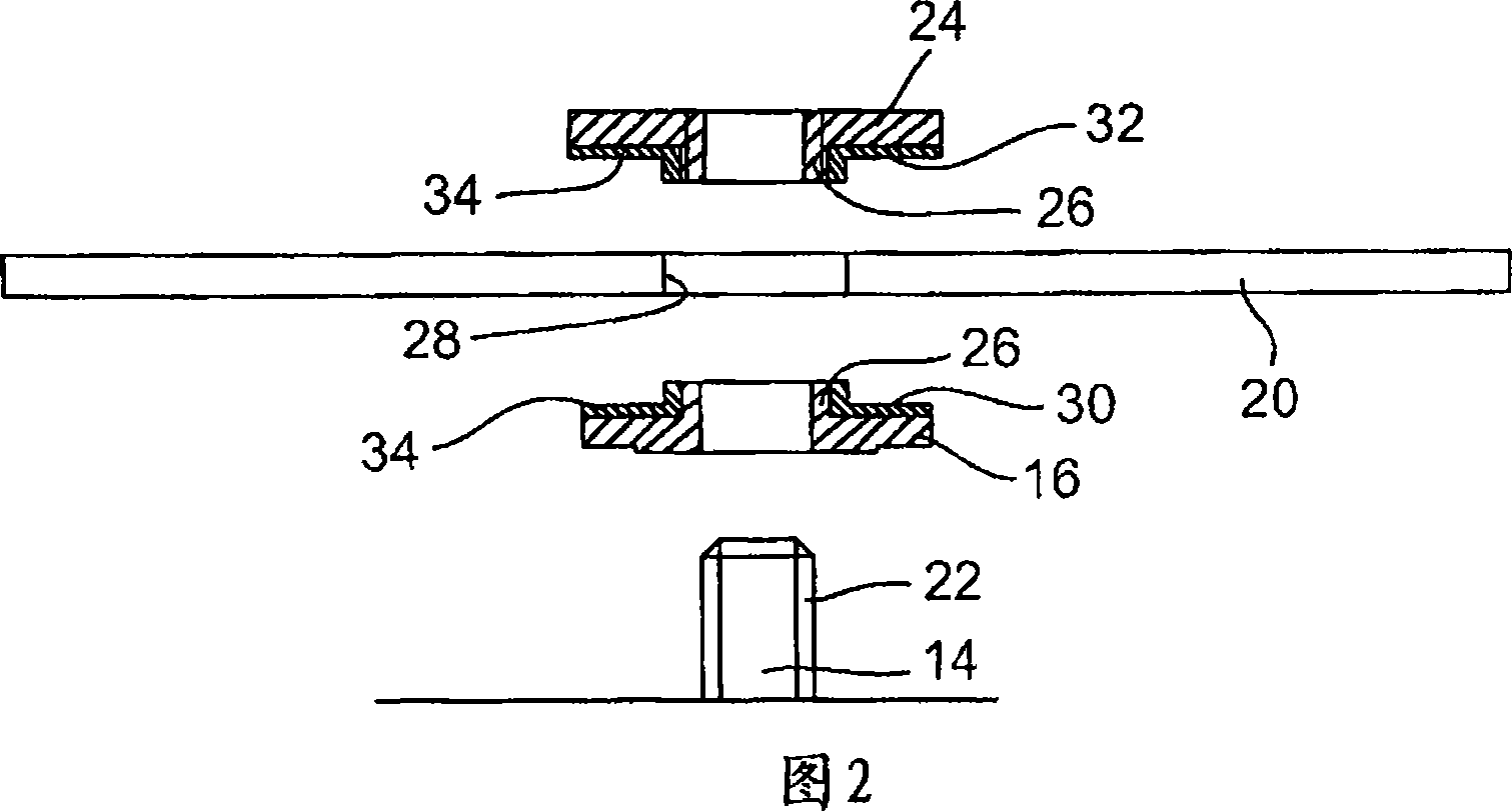
[0048] The universal angle grinder schematically shown in FIG. 1 includes a drive unit 10 and a handle 18 , the drive unit drives a transmission spindle 14 through a bevel gear transmission. The drive spindle 14 has a fastening flange 16 as a bearing for the rotary tool 20 . The outer end of the drive spindle 14 has an outer thread 22 , onto which a lock nut 24 is screwed, so that the tool 20 is clamped between the fastening flange 16 and the lock nut 24 . The fastening flange 16 and the union nut 24 have mutually opposing clamping faces 30 , 32 ( FIG. 2 ), between which the tool 20 is clamped. The fastening flange 16 can be formed integrally with the drive shaft 14 or can be a separate part, the fastening flange being engaged with the drive shaft 14 in a detachable but rotationally fixed manner. Around the edge of its central bore or around the shaft body of the drive spindle 14 , the fastening flange 16 has a flange 26 for cooperating with the tool 20 . The lock nut 24 als...


PUM


Abstract

Thousands of process and equipment measurements are gathered by the modern digital process control systems that are deployed in refineries and chemical plants. Several years of these data are historized in databases for analysis and reporting. These databases can be mined for the data patterns that occur during normal operation and those patterns used to determine when the process is behaving abnormally. These normal operating patterns are represented by sets of models. These models include simple engineering equations, which express known relationships that should be true during normal operations and multivariate statistical models based on a variation of principle component analysis. Equipment and process problems can be detected by comparing the data gathered on a minute by minute basis to predictions from these models of normal operation. The deviation between the expected pattern in the process operating data and the actual data pattern are interpreted by fuzzy Petri nets to determine the normality of the process operations. This is then used to help the operator localize and diagnose the root cause of the problem.

Description

technical field [0001] The invention relates to a device for cutting and grinding, such as a universal angle grinder, having a drive spindle on which a rotating tool such as a grinding wheel, rough-grinding wheel or cut-off wheel is fixed. Fixing is usually carried out by means of two clamping parts, fastening flange and union nut. The fastening flange is formed in one piece with the drive shaft or is separable but fitted in a rotationally fixed manner therewith. A lock nut is screwed onto the end of the drive shaft. The tool is firmly clamped between the fastening flange and the union nut. The clamping part can also be a lower and an upper fastening flange, which are clamped relative to each other by means of a nut. [0002] The invention also relates to a clamping device and a rotary tool, such as a grinding wheel, a cutting wheel or a rough grinding wheel. Background technique [0003] When using a universal angle grinder without vibration dampers, vibrations are gene...

Claims


Application Information

Patent Timeline
IPC IPC(8): B24B23/02B24B45/00B24D5/16B23D47/00B23D61/02F16F7/00B24B41/00
CPCB24B23/028B24B41/007
Inventor 彼得・德根
Owner RHODIUS SCHLEIFWERKZEUGE
Learn More