Multi-phase current supplying circuit, driving apparatus, compressor, and air conditioner
A multi-phase current and circuit technology, which is applied to electrical components, output power conversion devices, and AC power input to AC power output, etc. Power consumption and effect of suppressing rise in voltage across both ends
- Summary
- Abstract
- Description
- Claims
- Application Information
AI Technical Summary
Problems solved by technology
Method used
Image

Examples
no. 1 Embodiment approach
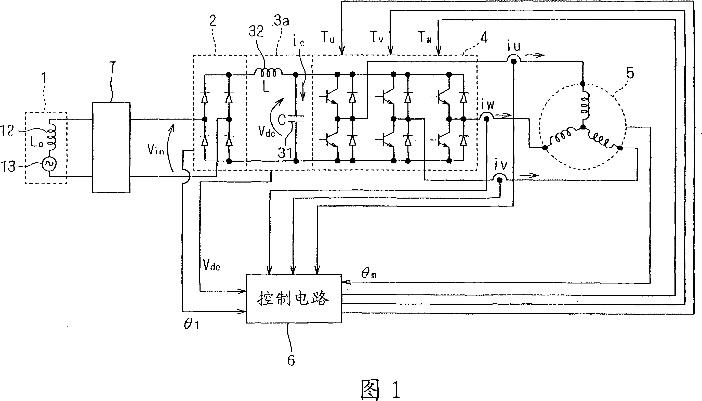
[0057] FIG. 1 is a circuit diagram showing a drive device according to a first embodiment of the present invention. This drive device has a motor 5 as a drive unit, and a multi-phase current supply circuit that supplies multi-phase current to the motor 5 .
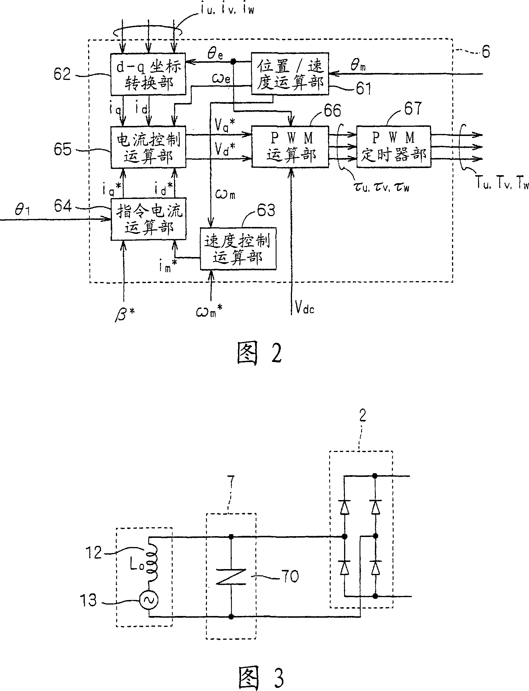
[0058] The multiphase current supply circuit has a diode bridge 2 , an intermediate circuit 3 , an inverter 4 , a control circuit 6 and a lightning arrester 7 . The diode bridge 2 is connected to the single-phase AC power supply system 1 via the lightning arrester 7, and the single-phase AC voltage V in are full-wave rectified. However, as described above, there is parasitic inductance in the power supply system 1 , so the inductor 12 connected in series with the AC power supply 13 represents the parasitic inductance. Here, the value of the parasitic inductance L 0 Use 230μH.
[0059] The diode bridge 2 has the function of performing full-wave rectification, and the AC voltage V in Full-wave rectification is performed...
no. 2 Embodiment approach
[0112] In the first embodiment, the inductor is connected in series with respect to the capacitor 31, thereby suppressing the charging current i from the diode bridge 2 to the intermediate circuit 3 c drastic changes. However, it is also possible to provide a bypass connected in parallel with the capacitor 31 and discharge excess current to the bypass.
[0113] FIG. 7 is a circuit diagram showing the configuration of the intermediate circuit 3 b having the bypass 33 . Also in this embodiment, the configuration shown in FIG. 1 is adopted, but the intermediate circuit 3 a is replaced by the intermediate circuit 3 b shown in FIG. 7 .
[0114] The intermediate circuit 3b has a capacitor 31 receiving across it the output of the diode bridge 2 and converting the rectified voltage v developed across the capacitor 31 dc output to inverter 4. The intermediate circuit 3 b also has a bypass 33 connected in parallel to the capacitor 31 .
[0115] In the bypass 33 is connected in serie...
no. 3 Embodiment approach
[0129] 12 and 13 are both circuit diagrams showing a part of the multiphase current supply circuit according to the third embodiment of the present invention. Here, the diode bridge 2, the inverter 4 and the lightning arrester 7 are omitted, but the structure is the same as that shown in FIG. 1 . Furthermore, in this embodiment, an intermediate circuit 3d (see FIG. 12 ) or an intermediate circuit 3e (see FIG. 13 ) is used instead of the intermediate circuit 3 in FIG. 1 .
[0130] The intermediate circuit 3d is configured such that, in the first embodiment, the bypass 34 connected in parallel to the capacitor 31 is added to the intermediate circuit 3a described using FIG. 1 , the intermediate circuit 3e is configured such that, in the second embodiment, In the intermediate circuit 3 b described using FIG. 7 , a bypass 34 connected in parallel to the capacitor 31 is added. Bypass 34 has switching elements namely transistor Q and resistor R B series connection.
[0131] The co...
PUM
 Abstract
Description
Claims
Application Information
 - Generate Ideas
- Intellectual Property
- Life Sciences
- Materials
- Tech Scout
- Unparalleled Data Quality
- Higher Quality Content
- 60% Fewer Hallucinations
Browse by: Latest US Patents, China's latest patents, Technical Efficacy Thesaurus, Application Domain, Technology Topic, Popular Technical Reports.
© 2025 PatSnap. All rights reserved.Legal|Privacy policy|Modern Slavery Act Transparency Statement|Sitemap|About US| Contact US: help@patsnap.com