Thread winding device and assembling method thereof

A winding device and assembly method technology, which is applied in coil manufacturing and other directions, can solve problems such as increased stray capacitance, easy disconnection of lead wires, and increased working hours, so as to reduce leakage magnetic flux and noise, and improve insulation withstand voltage , Reduce the effect of leakage flux

Inactive Publication Date: 2007-11-14
SANKEN ELECTRIC CO LTD
View PDF1 Cites 5 Cited by
  • Summary
  • Abstract
  • Description
  • Claims
  • Application Information

AI Technical Summary

Problems solved by technology

Therefore, the distance between the winding start and the winding end of the high-voltage coil (21) is close, so the stray capacitance between the terminals of the high-voltage coil (21) increases, and it is difficult to ensure the withstand voltage between the terminals stably. , since the lead-out wires of each coil (21, 22) are increased, there is a problem of easy disconnection
[0010] Wind the coil (21) for high voltage on the side (inside) of the middle legs (11c, 12c) of a pair of E-shaped cores (11, 12), and place both ends of each coil (21, 22) in two directions. When pulling out, although it is easy to ensure the withstand voltage between the terminals of the high-voltage coil (21), it is difficult to ensure that the two ends of the high-voltage coil (21) and the E-shaped cores (11, 12) and the high-voltage The insulation distance and creepage distance between the two ends of the coil (21) and the two ends of the low-voltage coil (22) cannot be miniaturized
[0011] Wind the coil (21) for high voltage on the side (outside) of the middle legs (11c, 12c) away from a pair of E-shaped cores (11, 12), and align the two ends of each coil (21, 22) to the same In the case of pulling out in the direction, although the insulation distance and the creepage distance between the two ends of the high-voltage coil (21) and the E-shaped core (11, 12) can be ensured by the cover, it is difficult to ensure that the high-voltage coil (21) ) and the insulation distance and creepage distance between the two ends of the low-voltage coil (22), there is a problem that it cannot be miniaturized
In addition, since both ends of the coils (21, 22) are drawn in the same direction, the number of man-hours increases, and it is difficult to stably ensure the withstand voltage between the terminals of the high-voltage coil (21). 22) The problem that the lead-out line is easy to break
[0012] Winding the coil (21) for high voltage on the side (outside) of the middle legs (11c, 12c) away from a pair of E-shaped cores (11, 12), the two ends of each coil (21, 22) are In the case of pulling out, although the insulation distance and creepage distance between the two ends of the high-voltage coil (21) and the E-shaped core (11, 12) can be ensured by the covering cover, it is difficult to ensure the high-voltage coil (21) ) and the insulation distance and creepage distance between the two ends of the low-voltage coil (22), there is a problem that it cannot be miniaturized
[0013] As mentioned above, it is difficult for the existing transformers shown in FIGS. 7 and 8 to sufficiently ensure the insulation distance between the high-voltage coil (21) on the secondary side and the low-voltage coil (22) on the primary side, as well as the creepage distance, Realize miniaturization, weight reduction and high withstand voltage
In addition, the high withstand voltage requires the separate use of an insulating cover (41), which has the disadvantages of high component costs and complicated assembly processes.

Method used


Image

  • Thread winding device and assembling method thereof
  • Thread winding device and assembling method thereof
  • Thread winding device and assembling method thereof

Examples


Embodiment Construction

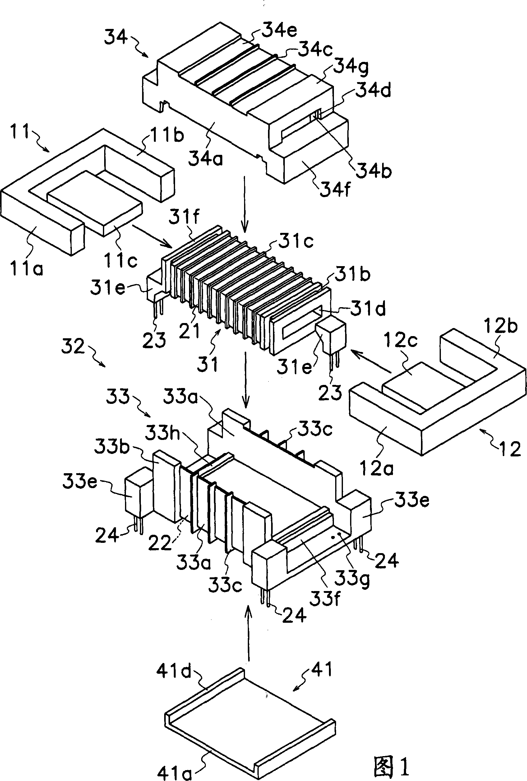
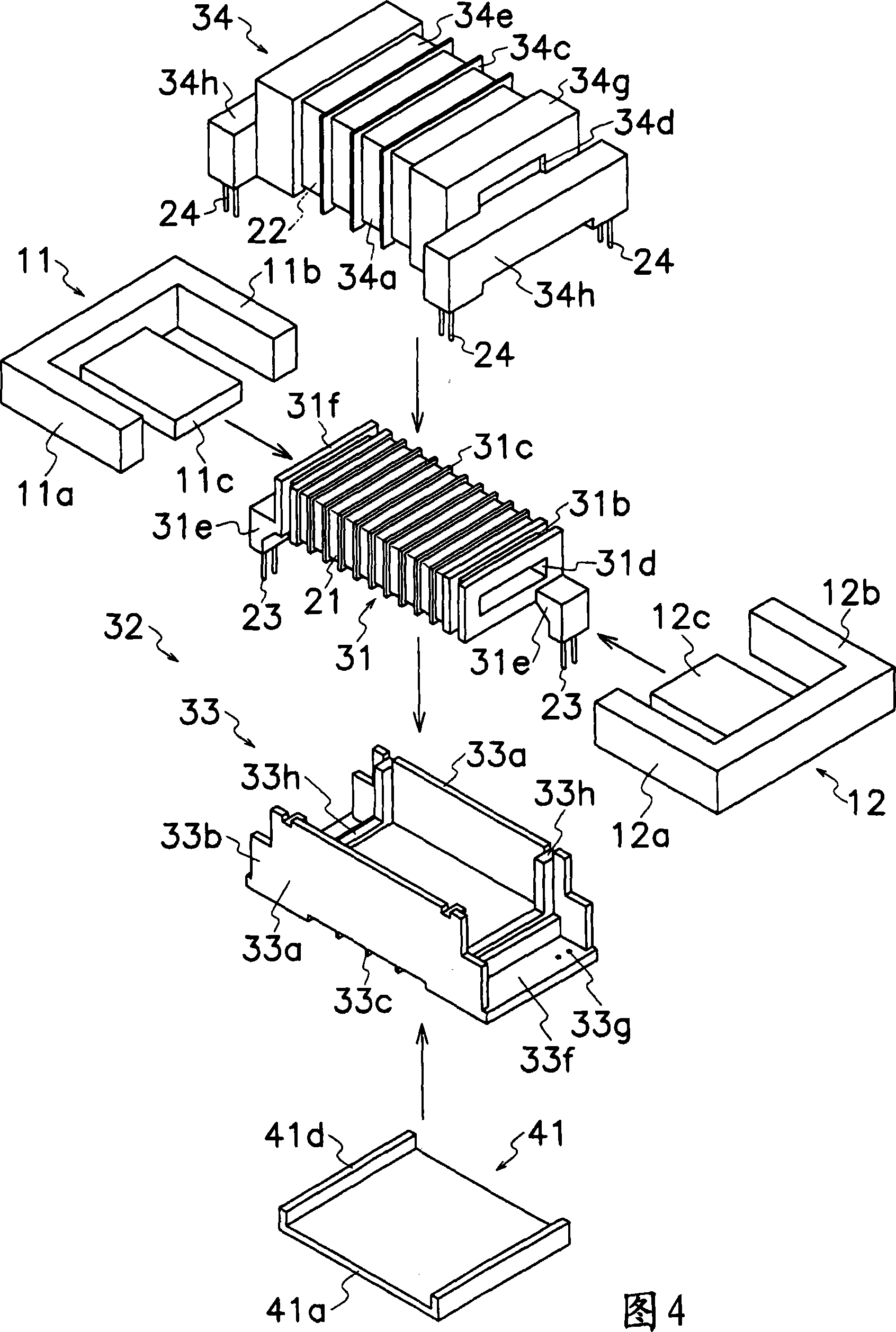
[0026] Hereinafter, an embodiment in which the winding device of the present invention is applied to a transformer for high voltage will be described with reference to FIGS. 1 to 6 . In FIGS. 1 to 6 , the parts that are substantially the same as those shown in FIGS. 7 and 8 are denoted by the same reference numerals, and description thereof will be omitted.

[0027] As shown in Figures 1 to 3, the transformer of this embodiment has a first bobbin (31), a second bobbin (32) and a pair of E-shaped cores (11, 12) as cores, the first winding The bobbin (31) has a cavity (31d) and the coil (21) for high voltage is wound on the outside; the second bobbin (32) is assembled in a manner surrounding the first bobbin (31) and the coil for low voltage ( 22) The package is on the outside; a pair of E-shaped cores (11, 12) are installed in the cavity (31d) of the first bobbin (31) and the outside of the second bobbin (32) to form a closed magnetic circuit. The first bobbin (31) has a cylin...


PUM


Abstract

An object of the present invention is to achieve downsizing, weight reduction, high withstand voltage, and cost reduction of winding devices such as transformers, reactors, and coils. The winding device of the present invention has a first bobbin (31), a second bobbin (32) and an E-shaped core (11, 12), the first bobbin (31) has a cavity (31d) and the high voltage The coil (21) is wound on the outside; the second bobbin (32) is assembled in a manner surrounding the first bobbin (31) and the low voltage coil (22) is wound on the outside; the E-shaped core (11, 12) Installed in the cavity (31d) of the first bobbin (31) and the outside of the second bobbin (32) to form a closed magnetic circuit, the second bobbin (32) has a housing (33) and A cover (34), the housing (33) has a bottom wall (33f) and a pair of side walls (33a) extending vertically upward from both sides of the bottom wall (33f); the cover (34) has a top wall (34e) And a pair of side walls (34a) protruding from both sides of the top wall (34e) vertically downward, the first bobbin (31) is arranged on a pair of side walls (34a) of the cover (34), the shell In the space of the second bobbin (32) formed by the bottom wall (33f) of the body (33) and the top wall (34e) of the cover (34).

Description

technical field [0001] The present invention relates to a winding device for a transformer, a reactor or a coil, etc., and particularly relates to a winding device and an assembly method suitable for a small high-frequency transformer and the like, and the small high-frequency transformer and the like have a function for cold cathode fluorescent discharge High-voltage coils for lighting devices such as tubes (CCFL). Background technique [0002] In recent years, cold cathode fluorescent tubes have been frequently used in display devices such as notebook computers and liquid crystal televisions due to the advancement of power saving in electronic devices and the like. In particular, the recent enlargement of LCD TVs requires CCFLs with a length exceeding 1 m. Therefore, the output voltage of transformers used in inverter circuits for CCFL lighting tends to increase. Moreover, in order to reduce brightness instability and increase the brightness of a picture on a liquid cryst...

Claims


Application Information

Patent Timeline
Patent Type & Authority Applications(China)
IPC IPC(8): H01F41/06
Inventor 横原映二中村正
Owner SANKEN ELECTRIC CO LTD
Why Eureka
Try Eureka