
Ejection forming device and its method

A technology for injection molding and molding products, which is applied in the field of injection molding devices that can solve the problem of silver marks, can solve problems such as inconvenience, lower product yield, and affect surface processing, so as to avoid silver marks and improve yield.

Inactive Publication Date: 2007-11-14
PEGATRON
View PDF0 Cites 10 Cited by
  • Summary
  • Abstract
  • Description
  • Claims
  • Application Information

AI Technical Summary

Problems solved by technology

[0004] However, since the traditional injection molding factory is usually a workplace with high relative humidity (70%RH~95%RH), and the injection environment of the traditional injection molding factory is often dusty, when the molded product after injection molding is dry and moisture-free, Molded products tend to absorb moisture and dust mixed in the air through capillary phenomenon, resulting in a lot of dirt and traces (commonly known as silver marks in the industry) in the molded products, which will affect the subsequent surface processing and lead to a decrease in product yield
[0005] This shows that above-mentioned existing injection molding device and method thereof obviously still have inconvenience and defect in structure and use, and urgently need to be further improved
In order to solve the above-mentioned problems, the relevant manufacturers have tried their best to find a solution, but no suitable design has been developed for a long time, and the general products do not have a suitable structure to solve the above-mentioned problems. This is obviously related. The problem that the industry is eager to solve

Method used


Image

  • Ejection forming device and its method
  • Ejection forming device and its method
  • Ejection forming device and its method

Examples


Embodiment Construction

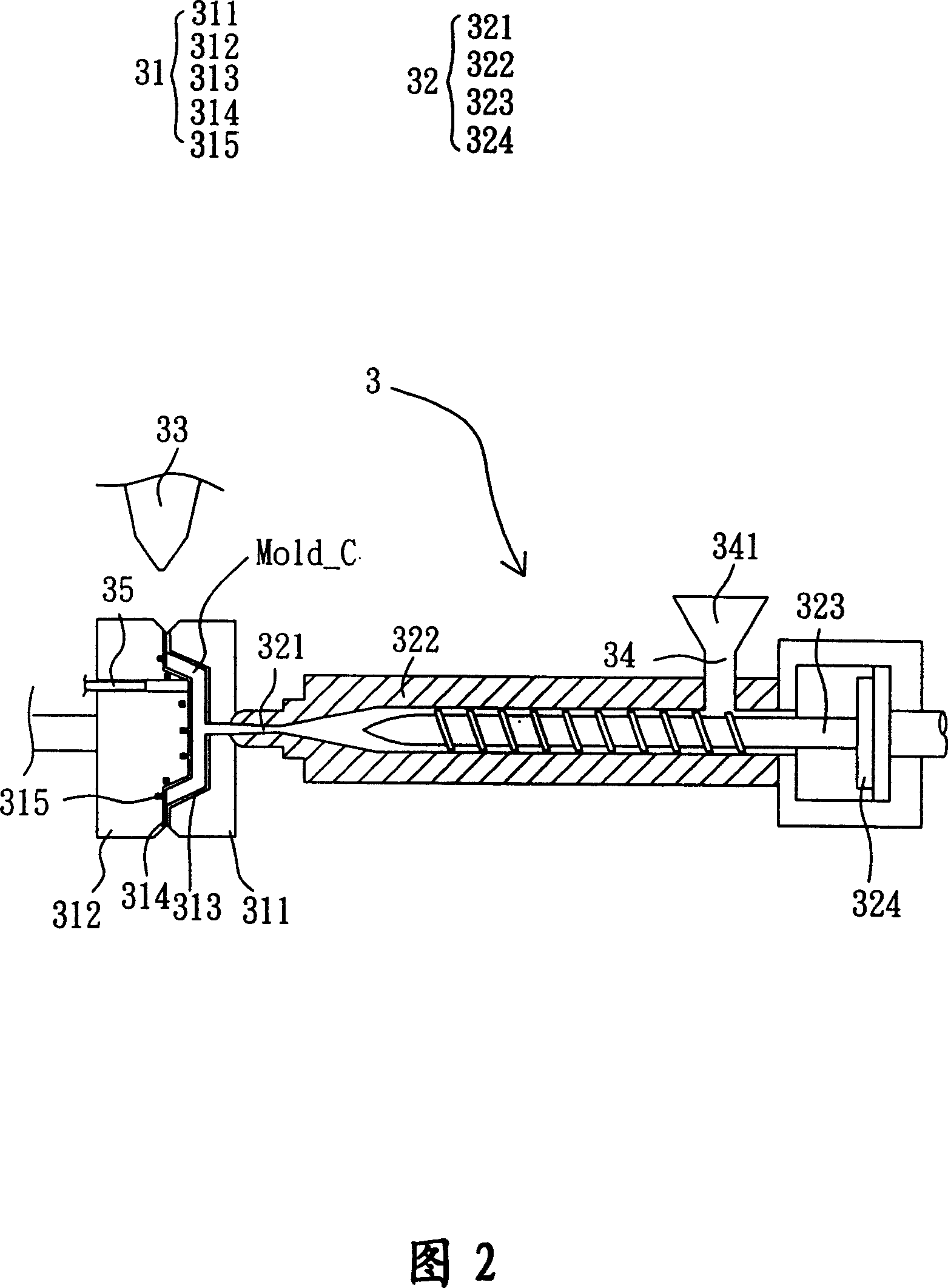
[0051] In order to further explain the technical means and effects of the present invention to achieve the intended purpose of the invention, the specific implementation, structure, characteristics and methods of the injection molding device and its method proposed according to the present invention will be described below in conjunction with the accompanying drawings and preferred embodiments. Its effect is described in detail below.

[0052] Please refer to FIG. 2 , the injection molding device 3 according to a preferred embodiment of the present invention includes a mold unit 31 , an injection unit 32 and a humidification unit 33 .

[0053] In this embodiment, the mold unit 31 has a fixed component 311 , a moving component 312 , a fixed side mold core 313 and a movable side mold core 314 . The fixing member 311 is opposite to the moving member 312 . The fixed side mold core 313 is disposed on the side of the fixed component 311 facing the moving component 312 , and the mov...


PUM


Abstract

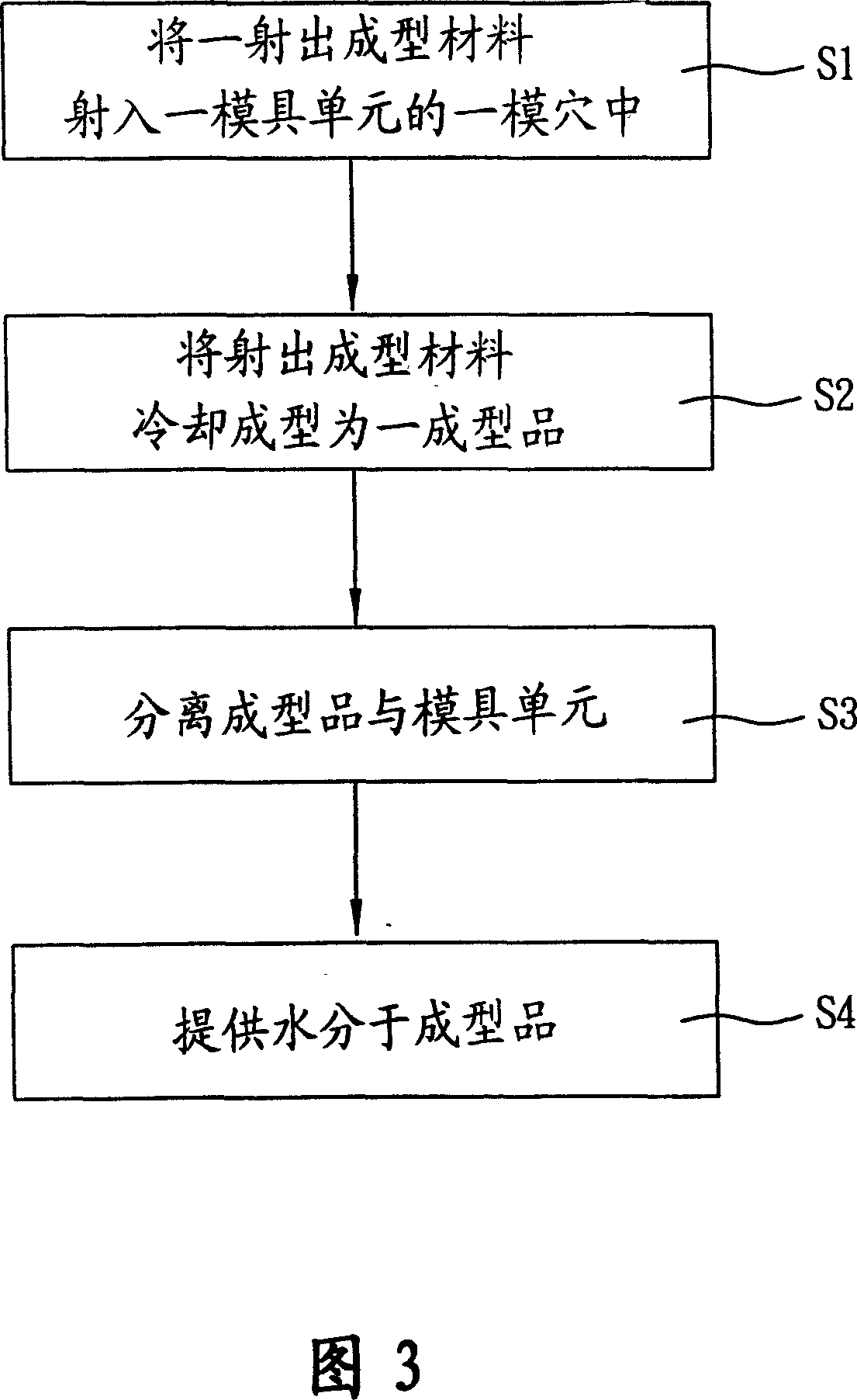
An emission forming device is used to form an emission forming material to a finished product. It contains a die unit, an emission unit and a humidifying unit. The die unit has a die point. The emission unit has a nozzle. The nozzle locates on one side of the way pipe and connects it with the die point. The humidifying unit is adjacent to the die unit for providing moisture. The emission forming materials enter the nozzle through the way pipe to jet into the die point and form the finished products by cooling. The materials separate from the die unit to make the humidifying unit providing moisture for the finished products.

Description

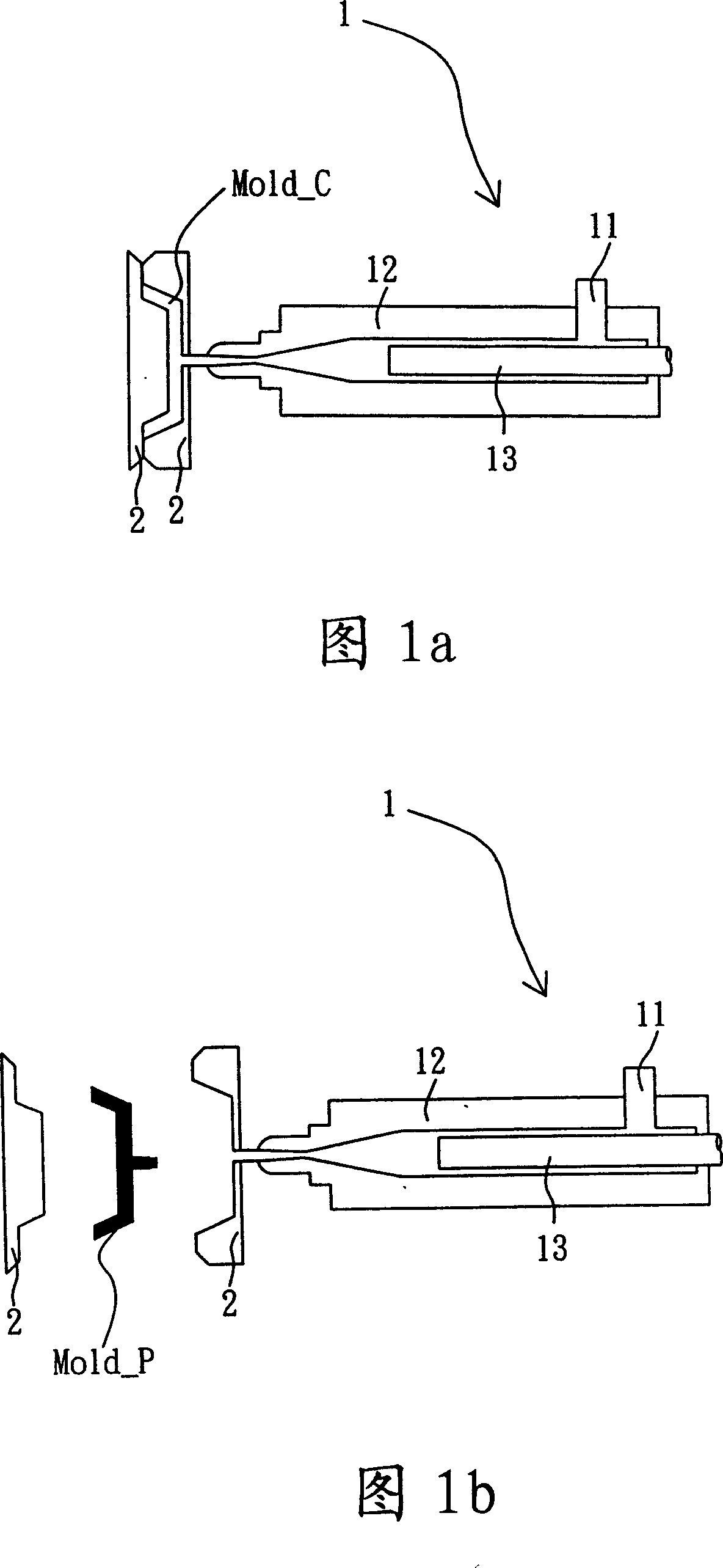
technical field [0001] The present invention relates to an injection molding device and its method, in particular to an injection molding device and its method which can solve the problem of silver marks. Background technique [0002] With the development of human material civilization, the method of using molds to manufacture products has become an indispensable technology for life. At present, the methods of using molds to manufacture products are mainly divided into injection molding, compression molding, blow molding and foam molding, etc. Among them, injection molding has the advantages of short manufacturing time, complex shapes and low prices, and has gradually become an unavailable Alternative manufacturing techniques. [0003] Please refer to FIG. 1a and FIG. 1b . FIG. 1a and FIG. 1b are known injection molding devices 1 . The known injection molding method is described below using FIG. 1a and FIG. 1b . First, a plastic material is poured into a feed port 11 for d...

Claims


Application Information

Patent Timeline
IPC IPC(8): B29C45/17B29C45/74B29C45/33B29C45/40B29C45/50
Inventor 张木财陈富明
Owner PEGATRON
Learn More