
Metod for tracing protocol stack state machine switching

A state switching and state machine technology, applied in the field of network communication, can solve the problems of multiple storage spaces, unrealizable functions, occupation, etc., and achieve the effect of improving system efficiency and fast positioning

Inactive Publication Date: 2007-11-07
ZTE CORP
View PDF0 Cites 9 Cited by
  • Summary
  • Abstract
  • Description
  • Claims
  • Application Information

AI Technical Summary

Problems solved by technology

[0011] 1) Statistics and counting information can only be used for quantification, not timing and qualitative
[0012] 2) Although the log record information is comprehensive, after the system has been running for a long time, it may record a large number of repeated state switching information, which takes up too much storage space and is very inconvenient to retrieve
However, the prior art cannot realize these functions due to the above-mentioned drawbacks

Method used


Image

  • Metod for tracing protocol stack state machine switching
  • Metod for tracing protocol stack state machine switching
  • Metod for tracing protocol stack state machine switching

Examples


Embodiment Construction

[0033] Preferred embodiments of the present invention are described in detail below.

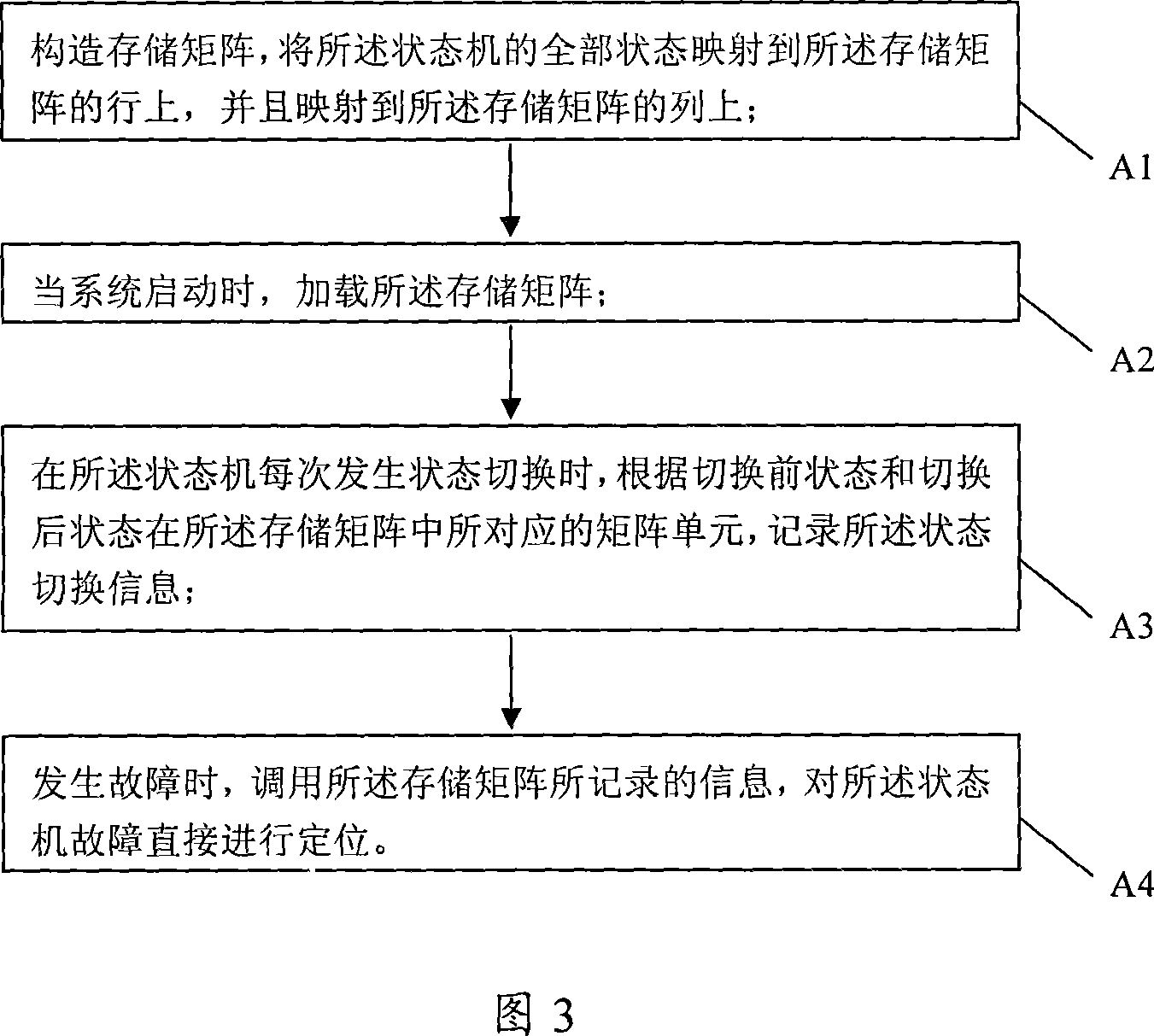
[0034] As shown in FIG. 3 , the present invention provides a method for tracking protocol stack state machine switching, which includes the following steps.

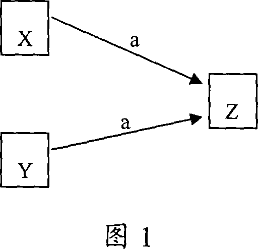
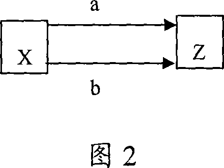
[0035] A1. Construct a storage matrix, and map all states of the state machine to rows of the storage matrix and to columns of the storage matrix. The matrix is ​​just a logical concept. Which data structure is used for storage is not the focus of this patent. Similarly, the form in which the content of the matrix is ​​stored in the storage medium is not the focus of this patent. Loading and saving to A database, a binary file or a text file can be used; when constructing the storage database, all the storage units of the storage database are respectively mapped to a two-dimensional combination of all the states of the state machine. Using a matrix to express the transition relationship between states belongs to the prior art, and wil...


PUM


Abstract

A method for tracking switchover of protocol stack stator includes setting up storage matrix mapping all states of stator onto lines and columns of storage matrix, loading storage matrix when system is started up, recording state switchover information in corresponding matrix unit of storage matrix according to states before and after switchover when state switchover is occurred on stator at each time and calling on information recorded by storage matrix to make positioning directly on fault of stator when fault is occurred on stator.

Description

technical field [0001] The invention relates to the field of network communication, in particular to a method for holographic tracking of a protocol automaton. Background technique [0002] In the protocol stack (Protocol Stack) of network communication, each layer uses a state machine to control the communication between peer entities. The protocol state machine is a deterministic finite automaton. A Deterministic Finite Automaton (DFA) M is a quintuple (Q, Σ, δ, q0, F) consisting of the following elements: [0003] 1) Finite state set Q; [0004] 2) Finite input set ∑; [0005] 3) Transfer function δ: Q×∑→Q, used to describe the possibility of each state in the system transitioning to other states, as long as the event occurs, the transition will occur; [0006] 4) Initial state q0; [0007] 5) The terminal state set F, F is included in Q. [0008] Starting from the initial state q0, the automaton processes input events one by one, and determines the next state of th...

Claims


Application Information

Patent Timeline
Patent Type & Authority Applications(China)
IPC IPC(8): H04L29/06H04L12/24
Inventor 周建波
Owner ZTE CORP
Learn More