Moveable solar range supporting mechanism

A technology for solar cookers and cooktops, applied in the field of solar energy devices, can solve problems such as inconvenient use and operation, low utilization rate of heat energy, immobility, etc., and achieve the effects of easy operation and improved thermal efficiency

Inactive Publication Date: 2007-10-31
都本强
View PDF0 Cites 1 Cited by
  • Summary
  • Abstract
  • Description
  • Claims
  • Application Information

AI Technical Summary

Problems solved by technology

[0002] During the use of the solar cooker in the prior art, due to the influence of the center of gravity, the adjustable range of the inclination angle of the reflective surface is small, and in addition, it cannot be moved, and the sunlight cannot be fully and effectively used, the heat energy utilization rate is low, the thermal efficiency is poor, and the use and operation are inconvenient Has yet to commercialize portable solar cookers

Method used


Image

  • Moveable solar range supporting mechanism
  • Moveable solar range supporting mechanism
  • Moveable solar range supporting mechanism

Examples


Embodiment Construction

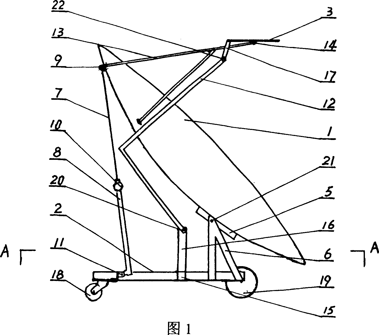
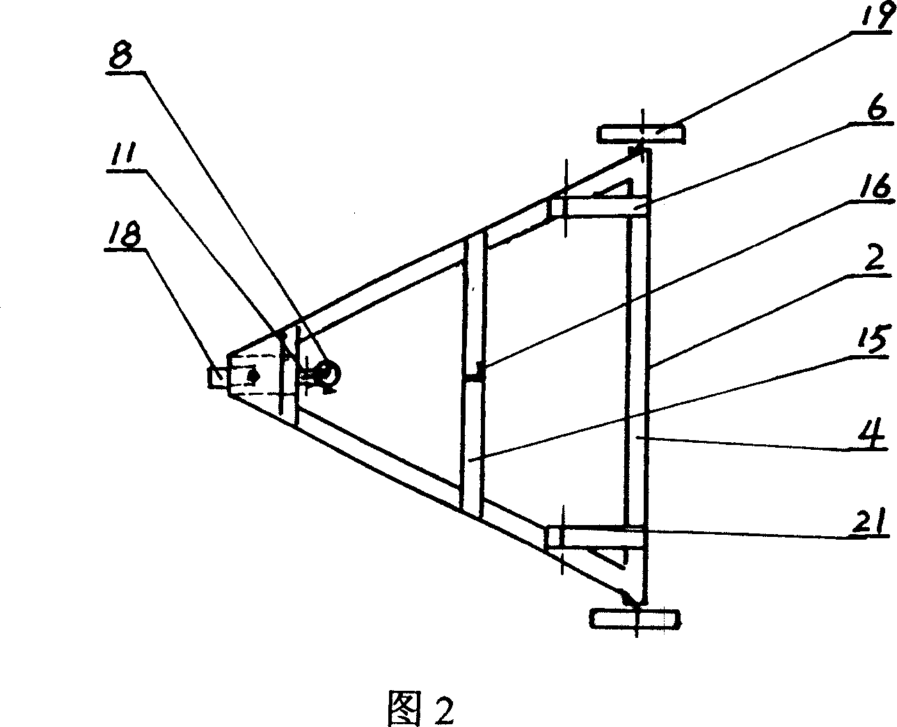
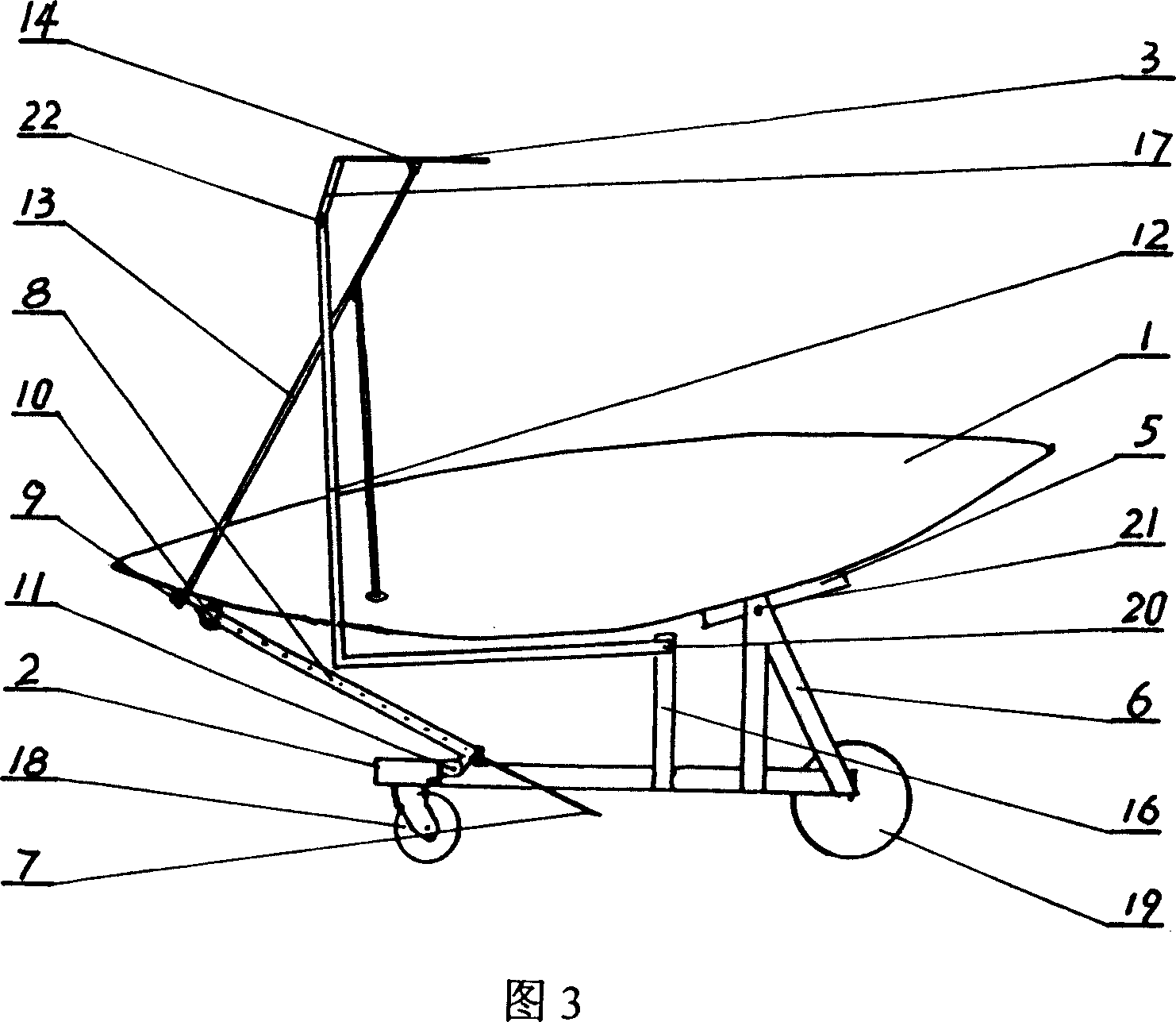
[0013] Referring to Fig. 1, the present invention comprises cooktop 1, chassis 2, pot ring 3, is characterized in that cooktop 1 is provided with support 5, telescopic rod seat 9, pot stand 13; Chassis 2 is provided with support 6, casing seat 11. The beam 15 is provided with a hinge 21 on the support 6 and is hinged with the support 5. A telescopic rod 7 and a sleeve 8 are arranged between the casing seat 11 and the telescopic rod seat 9. The cross beam 15 is fixed with a pillar 16, and the pillar Hinge 20 is arranged on 16; Chassis 2 is triangular, and universal wheel 18 is equipped with on its triangular top, and directional wheel 19 is equipped with at bottom edge 4 two ends; A horizontally fixed extension rod 17 is provided, and a hinge 22 is arranged on the extension rod 17 , and a translational pull rod 12 is arranged between the hinge 22 and the hinge 20 on the pillar 16 . A casing 8 is hinged on the casing seat 11, and a locking device 10 is provided on the casing 8. ...


PUM


Abstract

The invention discloses a movable solar stove support structure, comprising a strove surface, a chassis and a stove ring, characterized in that the strove surface is provided with a support base, an adjustable pole base and a stove frame, the support base is provided with a coupling head, the chassis is provided with a support frame, a cover tube base and a beam, the chassis is a triangle, the top ends of the triangle is provided with an universal wheel, the two ends of the bottom is provided with a directional wheel, the stove ring is provided with a coupling head, a prolonged pole horizontally fixed. The invention makes the stove surface absorb the solar lights at a maximum extent, to make the stove follow every direction of the sun, and the absorbed energy is reflected to the location of the stove ring via the stove surface, to maintain the stove ring always locate at the focus point of the reflected rays and in a horizontal condition. The invention could sufficiently and effectively use the solar energy, to improve the heat efficiency, the operation is easy, the structure is simple, the produce cost is low and it is easy to realize commercial mass production.

Description

technical field [0001] The invention relates to a device applying solar energy in the energy field, in particular to a movable solar cooker supporting mechanism. Background technique [0002] In the process of using the solar cooker in the prior art, due to the influence of the center of gravity, the adjustable range of the inclination angle of the reflecting surface is small, and in addition, it cannot be moved, and the sunlight cannot be fully and effectively used, the heat energy utilization rate is low, the thermal efficiency is poor, and the use and operation are inconvenient. Commercialization of portable solar cookers has not yet been possible. Contents of the invention [0003] An ideal solar cooker must absorb sunlight to the maximum extent; reflect the absorbed energy to the focal point through the reflective surface, which is commonly referred to as the position of the pot ring; control the highest point and the lowest point of the pot ring and keep the pot ring...

Claims


Application Information

Patent Timeline
IPC IPC(8): F24J2/52F24S20/30
CPCF24J2/02F24J2/36F24J2/541Y02B40/18Y02E10/47F24S20/30F24S20/50F24S30/425F24S50/20
Inventor 都本强
Owner 都本强
Why Eureka
Try Eureka