Eureka AIR delivers breakthrough ideas for toughest innovation challenges, trusted by R&D personnel around the world.

Stepping motor for generating vibration

A technology of stepping motor and direction of rotation, applied in the direction of motor generator control, synchronous machine, electrical components, etc., can solve problems such as uncertainty, and achieve the effect of maintaining torque and increasing starting torque

Inactive Publication Date: 2007-10-24
MINEBEA MOTOR MFG
View PDF3 Cites 3 Cited by
  • Summary
  • Abstract
  • Description
  • Claims
  • Application Information

AI Technical Summary

Problems solved by technology

Therefore, it is uncertain whether this technology can be applied to stepping motors loaded with eccentric weights and generating vibrations

Method used


Image

  • Stepping motor for generating vibration
  • Stepping motor for generating vibration
  • Stepping motor for generating vibration

Examples


Embodiment approach 1

[0136] Fig. 4(a) to Fig. 4(c) are the structural diagrams of the stepping motor with outer rotor type generating vibration of the present invention.

[0137] Fig. 4(a) is a B-B sectional view of Fig. 4(b); Fig. 4(b) is a A-A sectional view of Fig. 4(a); and Fig. 4(c) is a top view of the rotor frame.

[0138] The stepping motor 1 of the outer rotor type vibrating includes an interface base plate 2 , a cover 3 , a rotor 4 and a stator 5 .

[0139] By forming an insulating film on a metal plate, and by forming thereon necessary wiring such as a feeder to the coil and an opening (not shown) for fitting a boss (not shown) of the cover 3 , forming the interface substrate 2 . On the interface substrate 2, a second stator yoke 6b located on the interface substrate 2 side and a center yoke 6c serving as a third stator yoke in the stator yoke 6 are fixed via an insulating film. A protrusion (not shown) of the end face of the cylindrical portion 3b of the cap 3 is fitted in the openin...

Embodiment 1

[0183] (Effect of Embodiment 1)

[0184] Embodiment 1 can ensure the starting without prolonging the starting time and increasing the starting current.

[0185] Since the weight portion 13 is arranged at a part of the rotor frame 11 , the outer rotor type can share an accommodation space for the rotor frame 11 and the weight portion 13 . The counterweight part 13 can be arranged on the outermost side of the rotating part, so that the radius of the counterweight part 13 can be lengthened to generate strong vibration. Stepper motors, on the other hand, have no brushes and thus, like other brushless motors, stepper motors are essentially maintenance-free and can have a long life.

[0186] In addition, by controlling the rotation speed synchronously with the input pulse, the amount of vibration can be adjusted in a linear manner, and the stop time can be shortened.

[0187] Because of the single-phase drive, a drive pulse current having an alternating direction is input to the s...


PUM


Abstract

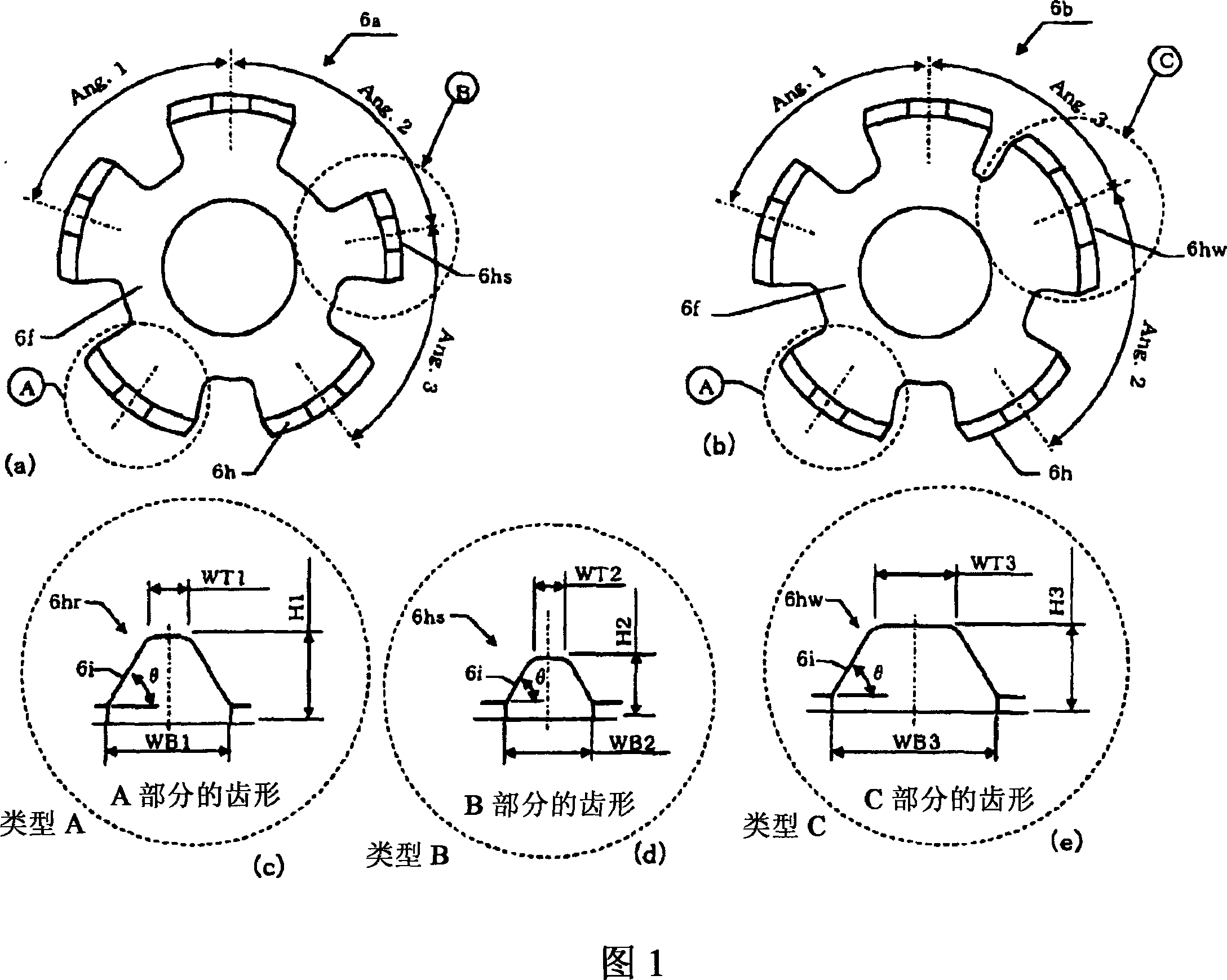
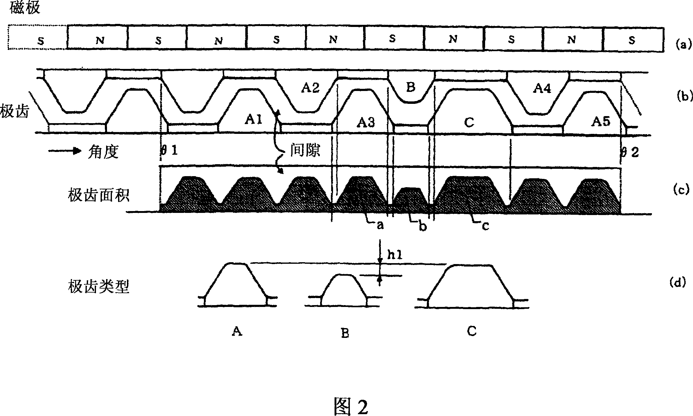
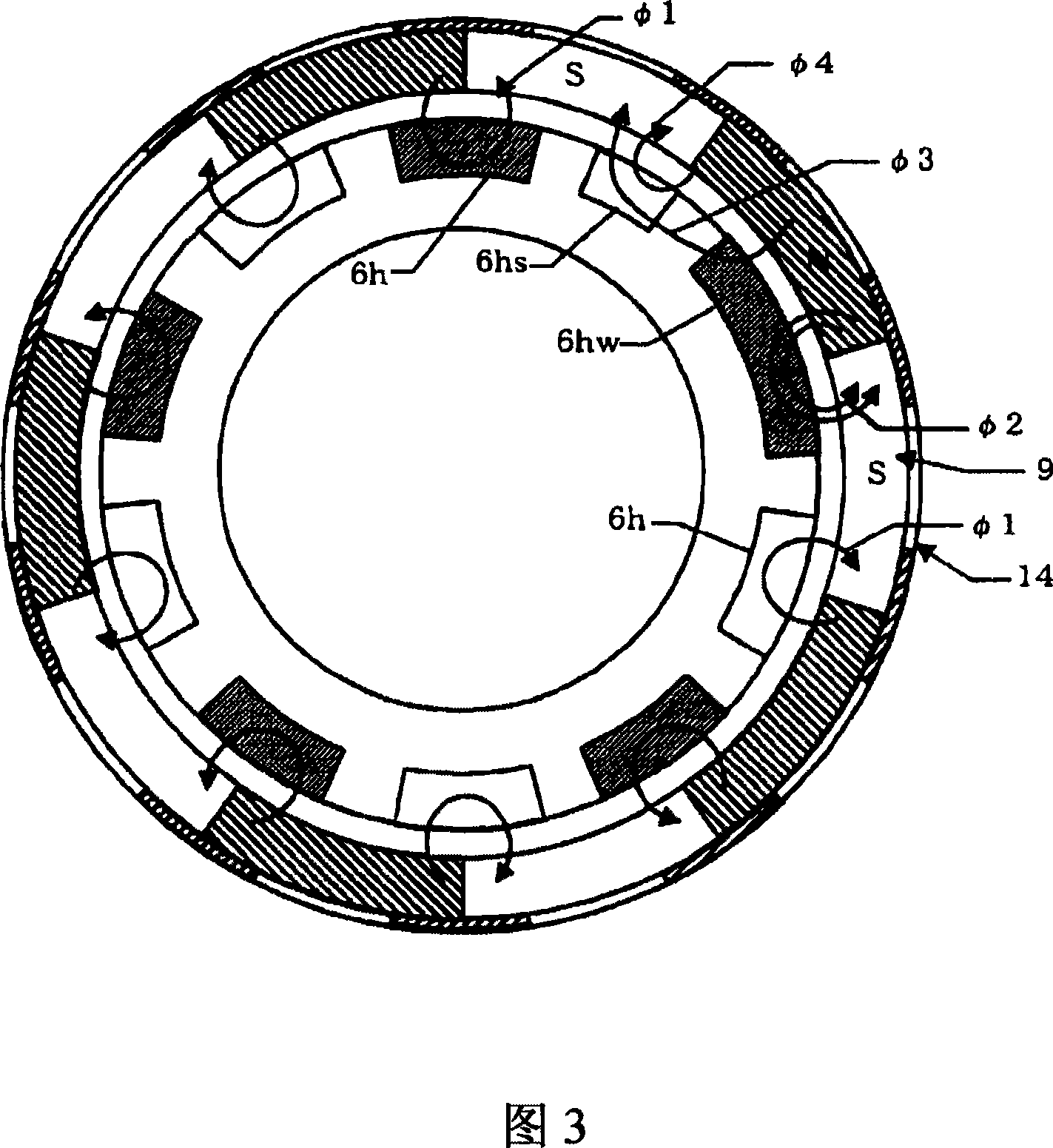
A stepping motor for generating vibration in which the stopping position can be securely held by increasing a detent torque. The pole teeth of one stator yoke of a set of one-phase stator yokes are formed in two types of pole teeth with different outermost face areas in the radial direction and the pole teeth of the other are formed in two types of pole teeth with different outermost face areas in the radial direction. One type of pole teeth of these stator yokes are formed in the same shape and the remaining two types of pole teeth which are not formed in the same shape are combined with each other and disposed so that the detent torque can be increased.

Description

technical field [0001] The invention relates to a vibrating stepping motor, which ensures that the vibrating stepping motor can maintain a stop position by increasing the starting torque, and more particularly relates to a PM single-phase stepping motor. Background technique [0002] Stepping motors are widely used because they are simple in structure and can be subjected to open control so that control circuit configuration can be simplified. PM stepper motors using permanent magnets are especially widely used due to their low application cost. These stepper motors require precise stop position control for proper starting. In the case of application regarding high-precision stop position control, a device is constructed to reduce the starting torque of the stepping motor, since this starting torque becomes a load when turning. [0003] However, in the case of a heavy load, for example, where a stepping motor generating vibration is loaded with a counterweight, it is diffi...

Claims


Application Information

Patent Timeline
Patent Type & Authority Applications(China)
IPC IPC(8): H02K37/12H02K37/14H02P8/32
CPCH02K37/12H02K7/063H02K21/227H02K29/03
Inventor 松原真朗佐藤和明梅原干雄津崎敏明
Owner MINEBEA MOTOR MFG
Why Eureka
Eureka Blog
Learn More