
Heat radiator

A technology of heat dissipation device and heat sink, which is applied in the direction of elastic/clamping device, cooling/ventilation/heating transformation, circuit layout on support structure, etc., which can solve the problems of low efficiency, fastening components and high fixed cost of heat sink, etc. Achieve the effect of simple assembly

Inactive Publication Date: 2010-08-25
FU ZHUN PRECISION IND SHENZHEN +1
View PDF0 Cites 0 Cited by
  • Summary
  • Abstract
  • Description
  • Claims
  • Application Information

AI Technical Summary

Problems solved by technology

The tapping of the thread on the fastening element and the bottom plate requires a special machine, and when locking, a special jig is required for positioning
The fixed cost of this type of fastening element and heat sink is relatively high, and the efficiency is relatively low

Method used


Image

  • Heat radiator
  • Heat radiator
  • Heat radiator

Examples


Embodiment Construction

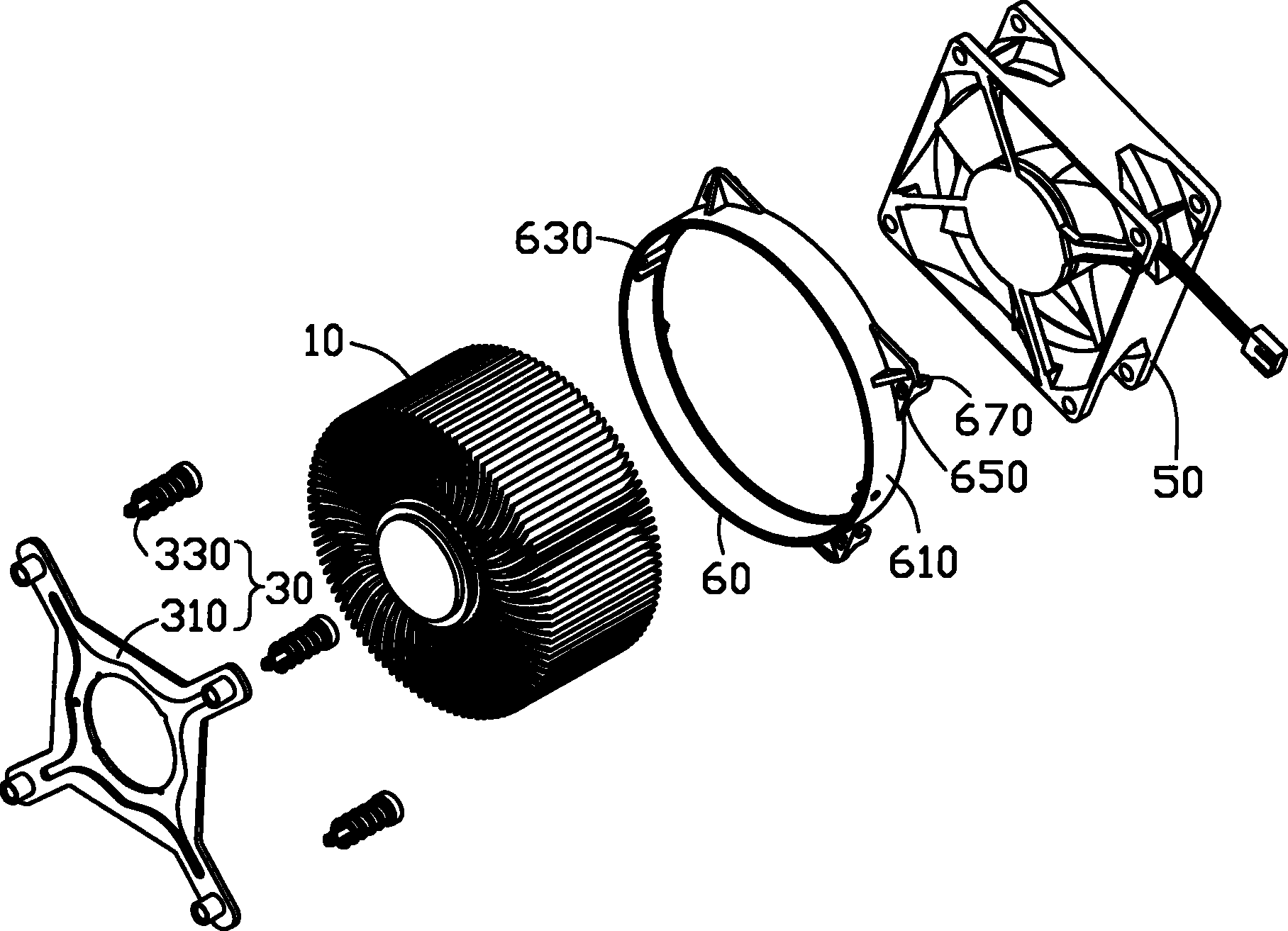
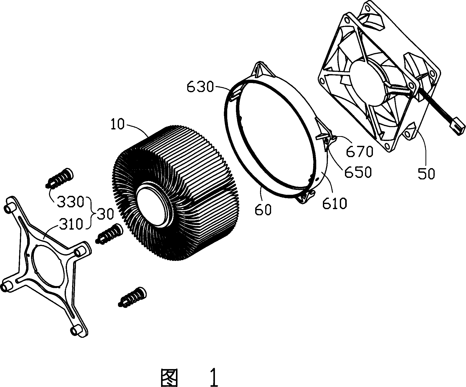
[0015] Please refer to FIG. 1 , the heat dissipation device is used for dissipating heat generated by an electronic component (not shown) mounted on a circuit board (not shown). The heat dissipation device includes a heat sink 10 , a buckle 30 for fixing the heat sink 10 to electronic components, a fan 50 mounted on the heat sink 10 , and a fixing frame 60 for fixing the fan 50 to the heat sink 10 .

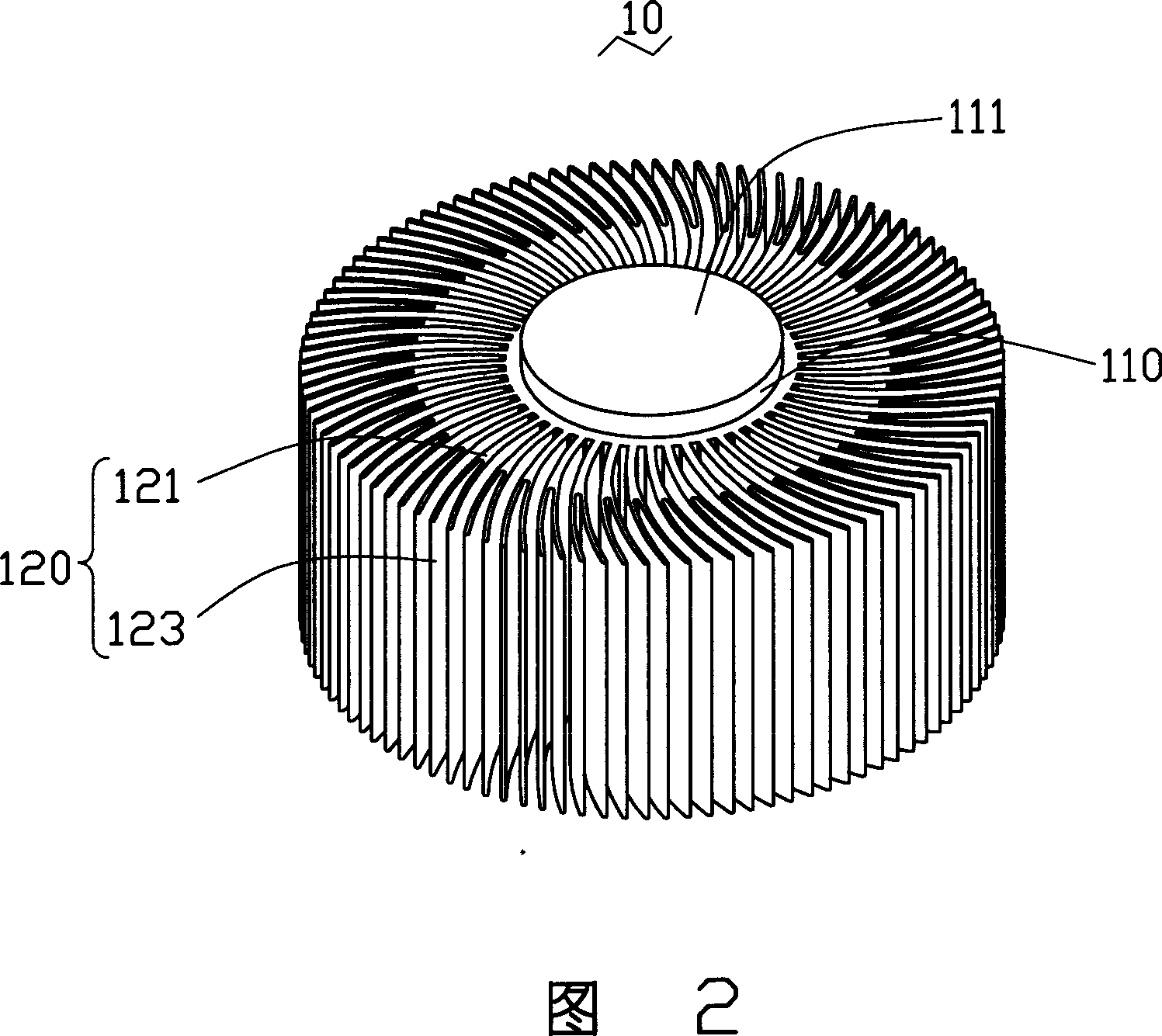
[0016] Please refer to FIG. 2 , the heat sink 10 includes a central cylinder 110 and a plurality of fins 120 radially extending from the outer peripheral surface of the central cylinder 110 . An extension portion 111 is further extended outwardly from the end of the central column 110 along its axial direction. The extension portion 111 protrudes from the fins 120 for contacting the heat-generating electronic components to absorb heat. The plurality of fins 120 are bent in a certain arc along the circumference of the cylinder 110 . Each fin 120 includes a stem portion 121 extend...


PUM


Abstract

The heat dispersion device for electronic element comprises: a heat radiator, and a gusset plate with a gap-round through hole fixing the radiator on the electronic element, wherein the radiator includes some fins and a heat absorption extended part with clip ear opposite to the gap. The extended part passes the opening and blocks on the gap by its block ear. This invention is simple and reliable.

Description

【Technical field】 [0001] The invention relates to a heat dissipation device, in particular to a heat dissipation device for dissipating heat from electronic components. 【Background technique】 [0002] As we all know, electronic components such as central processing units generate a lot of heat during operation. In order to prevent the temperature of the electronic component from rising due to the accumulation of heat and thus cause its operation to be unstable, the electronic component usually needs to be equipped with a heat dissipation device to assist in heat dissipation. Usually, in order to closely fix the heat sink to the electronic component, a fastening component is additionally required. [0003] A commonly used heat sink includes a bottom plate and a plurality of cooling fins arranged on the bottom plate. The above-mentioned fastening elements are usually locked to the bottom plate of the radiator by screws. In order to realize the fixing of the fastening elemen...

Claims


Application Information

Patent Timeline
Patent Type & Authority Patents(China)
IPC IPC(8): H05K7/20H05K7/12H01L23/367H01L23/40G12B15/06
Inventor 鲁翠军刘松水
Owner FU ZHUN PRECISION IND SHENZHEN
Learn More