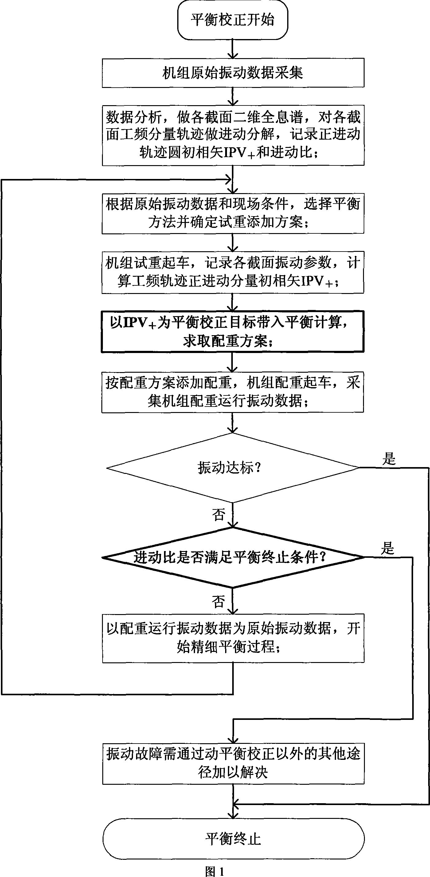
Precession vector based holographic on-spot dynamic balance method
An on-site dynamic balance and balance technology, which is applied in the static/dynamic balance test, measuring device, machine/structural component test, etc., can solve problems such as inability to judge and limit the rotor balance state, and achieve balance by avoiding multiple starts and stops Test, eliminate interference, and balance the effect of high precision
- Summary
- Abstract
- Description
- Claims
- Application Information
AI Technical Summary
Problems solved by technology
Method used
Image
Examples
example 1
[0061] The experiment was carried out on the No. 1 rotor test bench of the applicant's research institute.
[0062] Purpose:
[0063] It is verified whether the counterweight scheme of this method has the same balance accuracy as that of the traditional balance method under the condition that the rotor stiffness is the same.
[0064] The layout of the test bench is shown in Figure (4). The test bench is a single-span double-support structure. In the figure 1_X, 1_Y, 2_X and 2_Y are the axial installation positions of the eddy current sensor; K is the key phase device; P 1 ,P 2 There are two weighted discs; when viewed from the motor drive end to the free end of the rotor, the rotor rotates counterclockwise. The first-order criticality of the rotor is around 2000r / min, the second-order criticality is around 8000r / min, and the working (balance) speed of the rotor is 4000r / min.
[0065] The main purpose of the experiment is to demonstrate that the counterweight scheme obtained...
example 2
[0079] An Example Analysis of On-site Dynamic Balancing of Flue Gas Turbine in a Refinery
[0080] Purpose:
[0081] Test the application of this method in the dynamic balance of the unit under the action of combined faults and its comparison with the "holographic dynamic balance method".
[0082]Figure 5 is a schematic diagram of the structure of the flue gas turbine unit and the installation position of the sensor in an oil refinery. Section 1 is the front bearing of the hood, and section 2 is the rear bearing of the hood. In the figure, p is the film coupling position between the cigarette machine and the compressor. Due to the good vibration condition of the axial flow compressor and the elastic connection between the smoke machine and the compressor, the vibration on one side of the compressor was not considered in the process of solid vibration treatment. Figure 6a is the three-dimensional holographic spectrum of the two supports before the fault handling of the hood,...
example 3
[0089] This experiment was carried out on the No. 2 rotor balance test bench of our institute.
[0090] Purpose:
[0091] 1. Verify the balance effect of this method in combined faulty rotors, and compare it with the traditional balance method;
[0092] 2. To verify the reliability and validity of the equilibrium termination condition in this method.
[0093] The structure of the test bench, the arrangement of the sensors, the rotor steering, etc. are exactly the same as those of the No. 1 rotor balance test bench. between critical stages.
[0094] The main purpose of the experiment is to illustrate that the precession vector holographic balance method is not strictly dominant in the anisotropic stiffness of the system, or the rotor unbalance is not strictly dominant in the combination of faults affecting the rotor power frequency component vibration. Whether the balance scheme obtained by the method is significantly better than the scheme obtained from the information of t...
PUM
 Abstract
Description
Claims
Application Information
 - R&D Engineer
- R&D Manager
- IP Professional
- Industry Leading Data Capabilities
- Powerful AI technology
- Patent DNA Extraction
Browse by: Latest US Patents, China's latest patents, Technical Efficacy Thesaurus, Application Domain, Technology Topic, Popular Technical Reports.
© 2024 PatSnap. All rights reserved.Legal|Privacy policy|Modern Slavery Act Transparency Statement|Sitemap|About US| Contact US: help@patsnap.com


