
Rolling bearing lubricating method and device

A technology for rolling bearings and lubricating devices, which is applied in the direction of engine lubrication, bearing components, shafts and bearings, and can solve problems such as increased stirring resistance and temperature rise

Inactive Publication Date: 2007-10-24
NTN CORP
View PDF0 Cites 7 Cited by
  • Summary
  • Abstract
  • Description
  • Claims
  • Application Information

AI Technical Summary

Problems solved by technology

Also in this case, it may be possible to increase the amount of air and oil in the air oil to avoid insufficient lubrication, but if the amount of oil is increased, there is also an increase in agitation resistance and the risk of temperature rise

Method used


Image

  • Rolling bearing lubricating method and device
  • Rolling bearing lubricating method and device
  • Rolling bearing lubricating method and device

Examples


Embodiment Construction

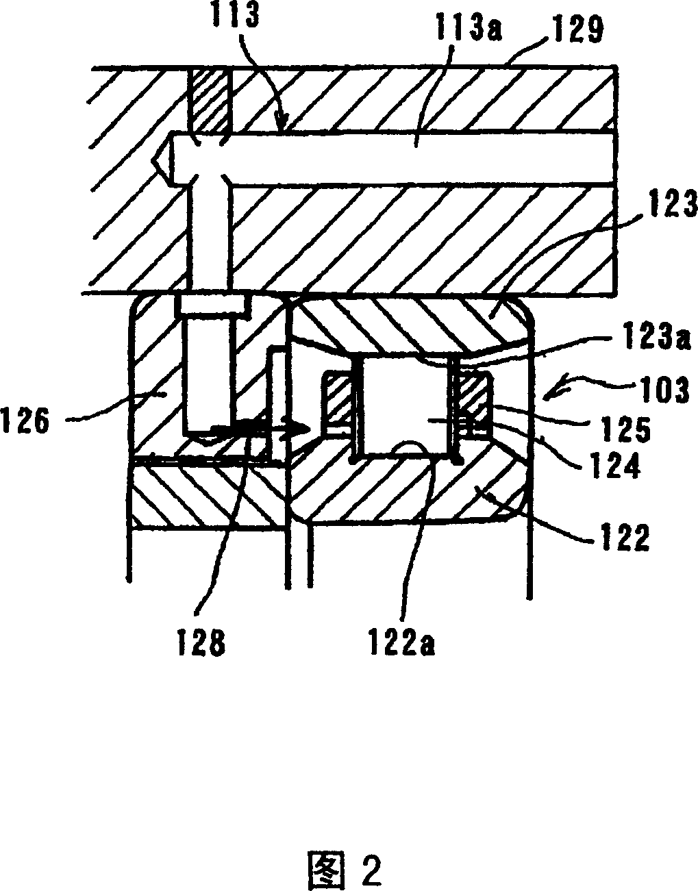
[0085] The method for lubricating a rolling bearing according to the first embodiment of the present invention will be described with reference to FIG. 1 and FIG. 2 . FIG. 1 shows the outline structure of a lubricating device used in this rolling bearing lubricating method. This lubricating device includes a lubricating oil supply mechanism 101 and a supply amount changing mechanism 102 . This lubricating oil supply mechanism 101 is a mechanism for supplying lubricating oil during operation of the rolling bearing 103 . The supply amount changing mechanism 102 is a mechanism for changing the supply amount of lubricating oil from the lubricating oil supply mechanism 101 in accordance with set conditions during the operation of the rolling bearing 103 .

[0086] The lubricating oil supply mechanism 101 intermittently injects air oil to the rolling bearing 103, and is configured as follows. The lubricating oil supply mechanism 101 includes a pump 105, which pressurizes the lubri...


PUM


Abstract

There is provided a lubricating method for a rolling bearing assembly capable of achieving a reliable lubrication and exhibiting a stable temperature rise. The method is for supplying a lubricant oil to the rolling bearing assembly during the operation thereof, in which in order to keep the temperature of a rolling bearing assembly ( 103 ) within a predetermined tolerance, the amount of the lubricant oil to be supplied during the operation is automatically or manually adjusted by means of a supply adjusting unit ( 102 ). Supply of the lubricant oil is performed in the form of an air / oil mixture by the use of a lubricant supply unit ( 101 ).

Description

[0001] This application is a divisional application of Chinese Invention Patent Application No. 03805213.X "Lubrication Method and Lubrication Device for Rolling Bearings" filed on March 3, 2003. technical field [0002] The present invention relates to a lubricating method, a lubricating device, an air-oil lubricating structure, and a main shaft assembly adopting the air-oil lubricating structure for a main shaft supporting part and a ball-head bolt supporting part of a processing machine. Background technique [0003] The purpose of the lubrication of rolling bearings is to form a thin oil film on the rolling and sliding surfaces to prevent direct contact between the inner and outer rings made of metal and the rolling elements made of metal, and to obtain the following effects. [0004] ①Reduce friction and wear; [0005] ②Discharge frictional heat; [0006] ③Prolong the life of the bearing; [0007] ④ prevent rust; [0008] ⑤Prevent the intrusion of foreign matter. ...

Claims


Application Information

Patent Timeline
IPC IPC(8): F16C33/66F16N7/32B23Q1/38B23Q11/12F16C33/58
Inventor 小杉太森正继植田敬一
Owner NTN CORP
Learn More