Built-in antenna and radio fixed station

A technology with a built-in antenna and a fixed platform, which is applied in the field of communication and can solve problems such as high cost, complicated manufacturing process, and large space occupation

Inactive Publication Date: 2007-10-17
ZTE CORP
View PDF0 Cites 1 Cited by
  • Summary
  • Abstract
  • Description
  • Claims
  • Application Information

AI Technical Summary

Problems solved by technology

Wireless fixed stations generally adopt external antenna design. Although this kind of antenna has good performance, it also has a series of problems such as high cost, large space occupation, and complicated manufacturing process. limit

Method used


Image

  • Built-in antenna and radio fixed station
  • Built-in antenna and radio fixed station
  • Built-in antenna and radio fixed station

Examples


Embodiment Construction

[0016] The specific implementation manners of the present invention will be described in detail below with reference to the accompanying drawings.

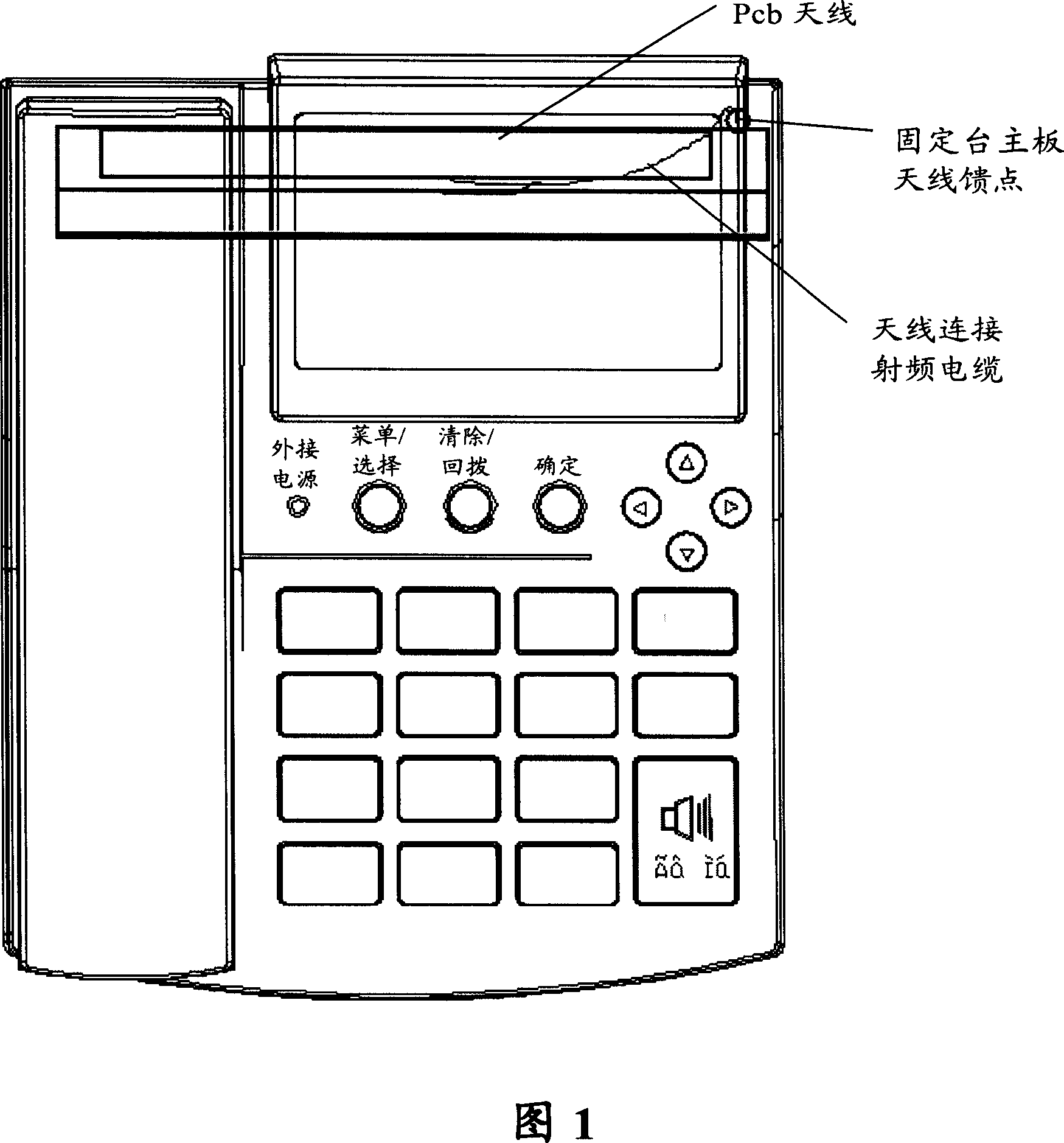
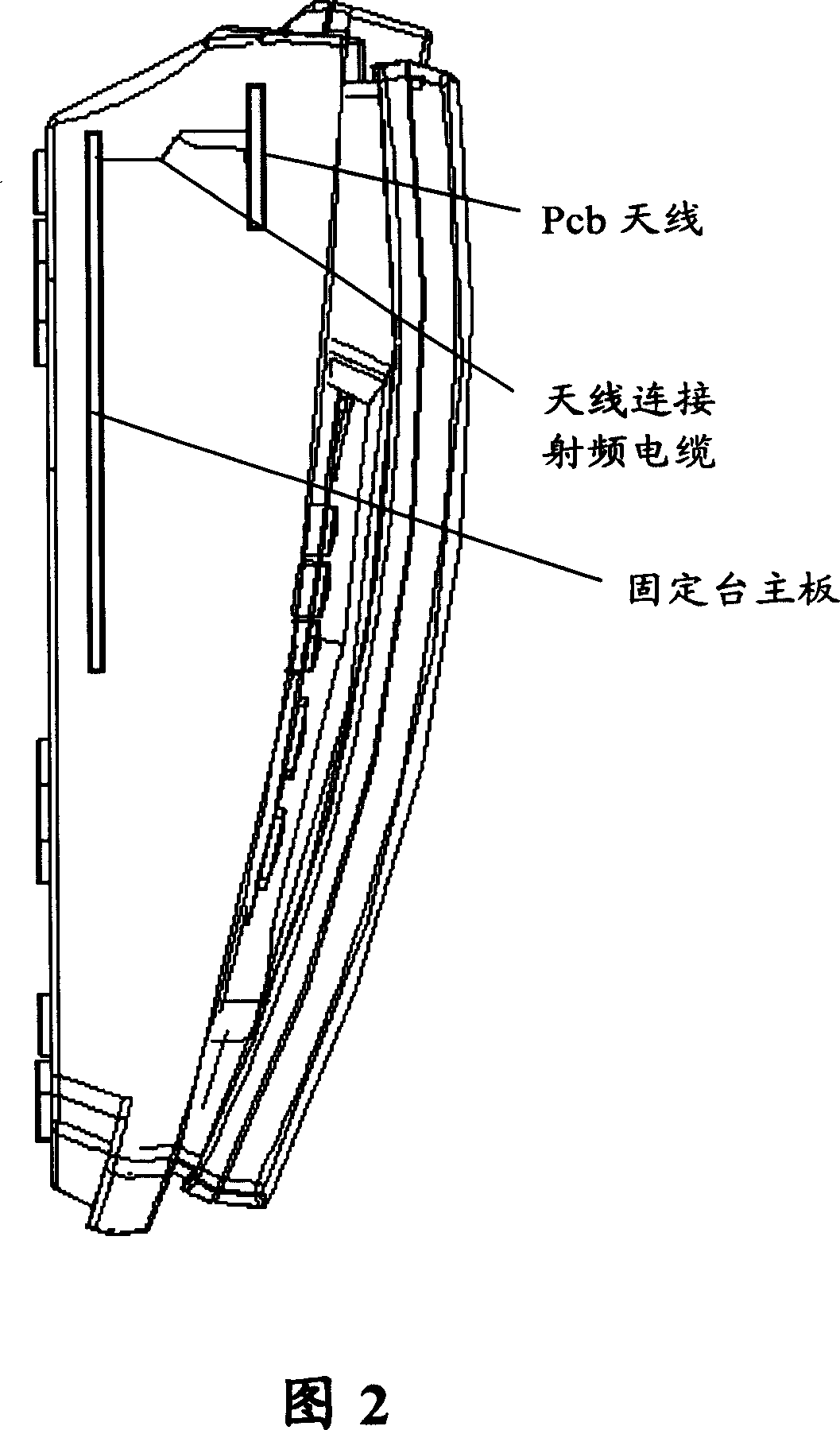
[0017] FIG. 1 shows a top view of an internal antenna according to an embodiment of the present invention, and FIG. 2 shows a side view of an internal antenna according to an embodiment of the present invention. As shown in Fig. 1 and Fig. 2, the built-in antenna according to the embodiment of the present invention consists of a 110*20mm single-sided copper-clad PCB board and a radio frequency cable. The PCB board completes the transmitting and receiving function of the antenna, and the radio frequency cable is used to connect the PCB board and the main board of the wireless fixed station. By adjusting the shape of the copper on the PCB and the position of the feed point of the RF cable, the effect of dual-frequency use can be achieved.

[0018] Compared with the external antenna and its required connectors, the cost of the PCB b...


PUM


Abstract

The invention discloses a built-in antenna comprising: a printed circuit board for receiving and transmitting signals; and a RF cable for connecting the printed circuit board to a device which is to be built-in. With the invention, an effect of using double-frequency can be realized.

Description

technical field [0001] The present invention relates to the communication field, and more specifically relates to a built-in antenna and a wireless fixed station. Background technique [0002] Currently, wireless fixed stations are being used more and more widely as an effective supplement to fixed telephones. Wireless fixed stations generally adopt external antenna design. Although this kind of antenna has good performance, it also has a series of problems such as high cost, large space occupation, and complicated manufacturing process. limit. [0003] The antenna design of wireless devices has been developing toward low cost, miniaturization, and modularization, so it is necessary to explore this aspect of antenna design for wireless fixed stations. [0004] At present, there are a few wireless fixed stations on the market that also use similar PCB built-in antennas, but they all work on single frequency. Contents of the invention [0005] In view of one or more probl...

Claims


Application Information

Patent Timeline
IPC IPC(8): H04Q7/32H04B1/38H01Q1/14H01Q1/24H01Q13/08H04B1/3827H04B1/50
Inventor 胡源李天才
Owner ZTE CORP
Why Eureka
Try Eureka