
Wave division multiplexer

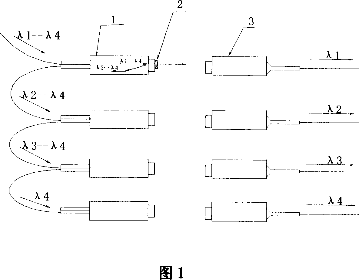
A wavelength division multiplexer and light wave technology, applied in the direction of wavelength division multiplexing system, etc., can solve the problems of high material cost, low device integration, large insertion loss, etc., to improve device integration, reduce components, insert The effect of low loss

Inactive Publication Date: 2007-10-17
SHANGHAI BROADBAND TECH
View PDF0 Cites 8 Cited by
  • Summary
  • Abstract
  • Description
  • Claims
  • Application Information

AI Technical Summary

Problems solved by technology

[0005] 1. Large insertion loss;
[0006] 2. Since each cascade has a certain loss, the loss among several channels is uneven;
[0007] 3. The structure of the device is complex, resulting in high material costs;
[0008] 4. Low device integration;

Method used


Image

  • Wave division multiplexer
  • Wave division multiplexer
  • Wave division multiplexer

Examples


Embodiment Construction

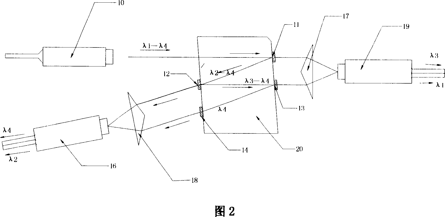
[0024] As shown in Figure 2, a kind of wavelength division multiplexer, it is a four-wavelength wavelength division multiplexer, comprises a single fiber collimator 10, four filters (11,12,13,14), two Double fiber collimator (16,19), two refracting prisms (17,18), a lens 20, described filter plate 11 and filter plate 12, filter plate 13 and filter plate 14 are arranged oppositely, and described lens 20 comprises A pair of parallel sides, the filters (11, 12, 13, 14) are all attached to the parallel sides of the lens 20. In this way, the four filters ( 11 , 12 , 13 , 14 ) are parallel to each other and distributed on both sides of the lens 20 to transmit the light of the wavelength to be separated and reflect the rest of the wavelength. The prism also plays the role of fixing four filters at the same time. In addition, the two refracting prisms (17, 18) are used to converge or disperse the optical paths of the two optical signals.

[0025] Wherein, the filters (11, 12, 13, 14...


PUM


Abstract

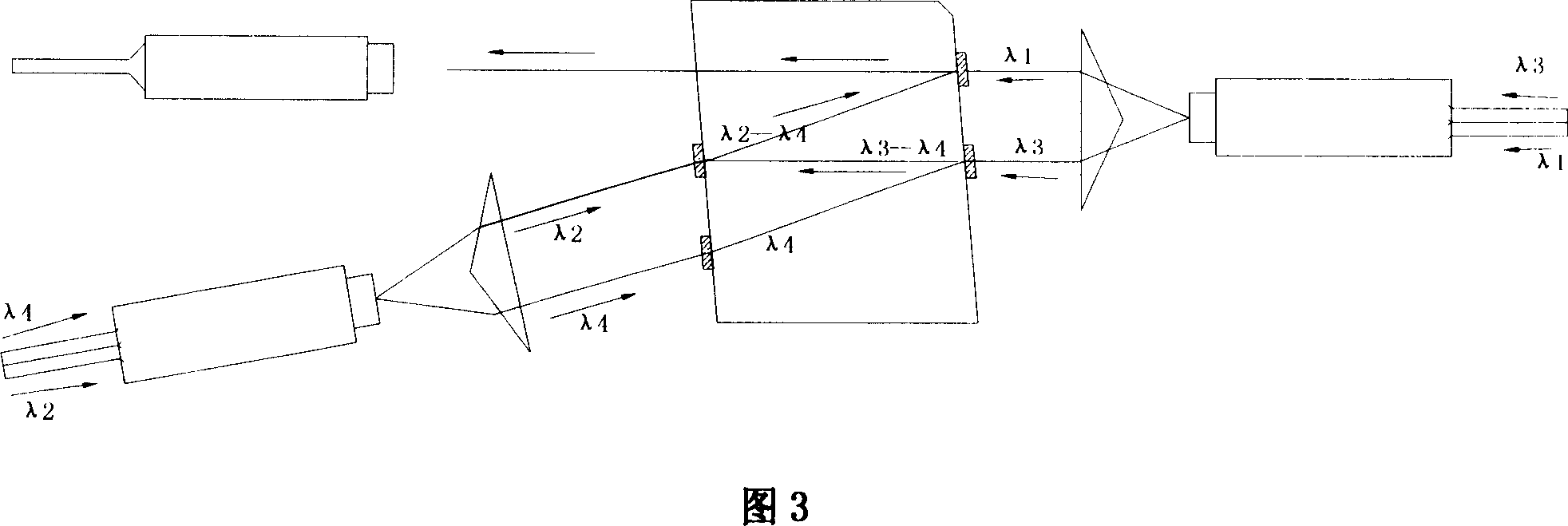
The present invention provides a wavelength division multiplexer including a plurality of filter plates each two of which are opposite with each other, a plurality of fiber collimators. The filter plates are described as the first, the second, the third, the fourth until the Nth, and the odd number sequence is opposite to the even number sequence. The light wave of a plurality of wavelengths achieves at the first filter plate through the fiber collimator when the light wave is divided; the light of the wavelength corresponding to the first filter plate is filtered out, while the light wave of other wavelength is reflected to the second filter plate opposite to the first filter plate; then the light of the wavelength corresponding to the second filter plate is filtered out, while the light wave of other wavelength is reflected to the third filter plate opposite to the first filter plate; the light of the wavelength corresponding to the third filter plate is filtered out and so on, and the whole process of wave dividing is completed as the prior steps. The wave combining of the light path can be realized when the light path is reverse according to the reversibility of light path. The wavelength division multiplexer in the present invention has low plug consumption and a low cost, and the number of the assembly parts is reduced and the density of integration of the parts is improved.

Description

technical field [0001] The invention relates to a passive optical device for optical fiber communication, in particular to a wavelength division multiplexing device. Background technique [0002] Wavelength division multiplexing (WDM) technology is to make full use of the huge bandwidth resources brought by the low-loss area of ​​single-mode fiber. According to the wavelength of each channel's light wave, the low-loss area of ​​the fiber can be divided into several channels, and the light wave is used as the signal. Carrier, at the sending end, a wavelength division multiplexer (combiner) is used to combine signal optical carriers of different specified wavelengths and send them into an optical fiber for transmission. At the receiving end, a wavelength division multiplexer (demultiplexer) is used to separate these optical carriers carrying different signals at different wavelengths. Since the optical carrier signals of different wavelengths can be regarded as independent of...

Claims


Application Information

Patent Timeline
Patent Type & Authority Applications(China)
IPC IPC(8): H04J14/02
Inventor 林清全徐光贵张罗成
Owner SHANGHAI BROADBAND TECH
Learn More