
Hybrid power supply

A mixed power and current technology, applied in circuit devices, battery circuit devices, circuits, etc., can solve problems such as deterioration of work and characteristics, unstable working area of ​​fuel cells, etc.

Inactive Publication Date: 2012-05-09
SANYO ELECTRIC CO LTD
View PDF2 Cites 0 Cited by
  • Summary
  • Abstract
  • Description
  • Claims
  • Application Information

AI Technical Summary

Problems solved by technology

[0004] Causes the fuel cell to work in an unstable working area and deteriorate characteristics, etc.

Method used


Image

  • Hybrid power supply
  • Hybrid power supply
  • Hybrid power supply

Examples


Embodiment Construction

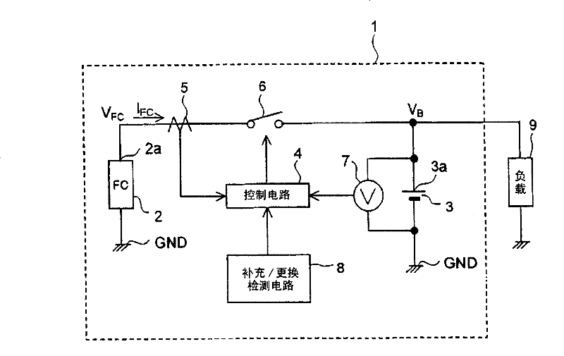
[0025] Hereinafter, embodiments of the present invention will be specifically described with reference to the drawings. In the respective drawings, the same symbols are assigned to the same components. figure 1 A block diagram showing a hybrid power supply device 1 (hereinafter simply referred to as "power supply device 1") according to the embodiment of the present invention.

[0026] The power supply device 1 includes: a fuel cell 2 ; a secondary battery 3 as an electric storage device; a control circuit 4 ; a current detector 5 ; a switch 6 ; a voltage detector 7 ; A load 9 is connected to the power supply device 1 .

[0027] The fuel cell 2 is a direct methanol fuel cell that uses methanol as a direct fuel to generate electricity. However, fuel cells other than the direct methanol type fuel cell may be used as the fuel cell 2 .

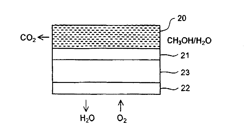
[0028] The fuel cell 2 is composed of a plurality of basic unit cells connected in series. figure 2 A schematic configuration diagram showin...


PUM


Abstract

A hybrid power supply device is provided with a fuel cell, an electric storage device that is connected in parallel to the fuel cell via a switch, and a control circuit that controls connection between output terminals of the fuel cell and the electric storage device by controlling on / off of the switch. Here, the control circuit controls the connection between the output terminals based on an output current of the fuel cell, and disconnects the output terminals when the output current of the fuel cell becomes equal to or smaller than a predetermined lower limit current while the output terminals are connected.

Description

technical field [0001] The present invention relates to a hybrid power supply device that uses a fuel cell and a power storage device such as a secondary battery together. Background technique [0002] In a hybrid power supply device using a fuel cell and a secondary battery together, generally, a diode is provided between the fuel cell and the secondary battery to protect the fuel cell as a reverse current prevention circuit. However, when a diode is provided, useless power is naturally consumed in the diode, which prevents the efficiency of the power supply device from being improved. [0003] Considering the above problems, the following solution is available: the fuel cell is connected in parallel with the secondary battery through a switch. Such a configuration is described in documents such as Japanese Patent Application Laid-Open No. 2004-342551 and Japanese Patent Laid-Open No. 8-163711. By connecting the fuel cell in parallel to the secondary battery via a switch,...

Claims


Application Information

Patent Timeline
Patent Type & Authority Patents(China)
IPC IPC(8): H02J7/34
CPCH01M8/04313H01M16/003H01M8/04955H02J7/34Y02E60/50H01M8/04589H01M8/04567H01M8/04
Inventor 濑尾和宏藤井雅也
Owner SANYO ELECTRIC CO LTD
Learn More