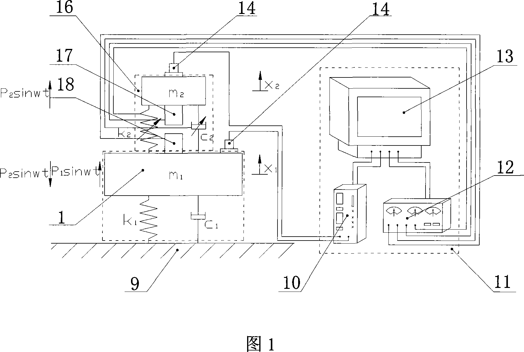
Rigidity-variable full-automatic power vibration-absorber
A technology of dynamic vibration absorber and variable stiffness, which is applied in the device of vibration reduction and noise control of electrical equipment, and in the field of machinery, which can solve the problem of high control energy, insufficient vibration absorption effect of semi-active control type vibration absorber, and narrow control bandwidth of passive control type vibration absorber and other problems, to achieve the effect of less energy consumption, easy control method, and small additional mass
- Summary
- Abstract
- Description
- Claims
- Application Information
AI Technical Summary
Problems solved by technology
Method used
Image
Examples
Embodiment 1
[0033] The variable stiffness fully active dynamic vibration absorber includes an actuator 16, a control unit 11, and a sensor 14. The vibration absorber control unit 11 includes a charge amplifier 10, a power amplifier 12, and a data acquisition and processing system 13, as shown in FIG. 1 .
[0034]As shown in Fig. 2 and Fig. 4, the executive components of the electric field force-driven rotary fully active variable stiffness dynamic shock absorber are composed of a vibration damping object 1; a base frame 2; a moving mass block 3; an annular guide rod 4; body 5; base 6; capacitor pole plate 8 connected to the moving mass for providing active force; capacitor pole plate 7 connected to the damping object for providing active force; excitation coil 21; bearing 24; outer ring guide Magnetic ring 25; Shaft coupling 26 is formed. The lower end of the base frame 2 is fixed on the damping object 1 with threads, and the upper end of the base frame 2 is connected with the base 6 with...
Embodiment 2
[0039] As shown in Figure 3 and Figure 4, the executive parts of the magnetic field force driven rotary fully active variable stiffness dynamic shock absorber are composed of a vibration damping object 1; a base frame 2; a moving mass block 3; an annular guide rod 4; Body 5; base 6; energized coil 20 connected to the moving mass block for providing active force; energized coil 19 connected with the vibration reduction object for providing active force; excitation coil 21; bearing 24; outer ring magnetic conduction Ring 25; Coupling 26 is formed. The lower end of the base frame 2 is fixed on the damping object 1 with threads, and the upper end of the base frame 2 is connected with the base 6 with bolts, and the ring guide rod 4 is connected with the base 6 through the bearing 24 so that the ring guide rod 4 can only Rotate around the axis, the outer ring magnetic ring 25 is fixed together with the base 6 through threaded connection, the magnetorheological elastomer 5 connects t...
PUM
 Abstract
Description
Claims
Application Information
 - R&D Engineer
- R&D Manager
- IP Professional
- Industry Leading Data Capabilities
- Powerful AI technology
- Patent DNA Extraction
Browse by: Latest US Patents, China's latest patents, Technical Efficacy Thesaurus, Application Domain, Technology Topic, Popular Technical Reports.
© 2024 PatSnap. All rights reserved.Legal|Privacy policy|Modern Slavery Act Transparency Statement|Sitemap|About US| Contact US: help@patsnap.com


