
Low power consumption axial magnetic bearing with redundant structure

A technology of axial magnetic bearing and redundant structure, applied in the direction of shaft and bearing, bearing, mechanical equipment, etc., can solve the problems of low reliability and high power consumption, and achieve the purpose of increasing the magnetic pole area, improving the bearing capacity and simple structure. Effect

Inactive Publication Date: 2007-10-17
BEIHANG UNIV
View PDF0 Cites 25 Cited by
  • Summary
  • Abstract
  • Description
  • Claims
  • Application Information

AI Technical Summary

Problems solved by technology

The permanent magnet bias axial magnetic bearing of the existing structure uses permanent magnets to generate the bias magnetic field, but it cannot achieve redundancy, so the reliability is low
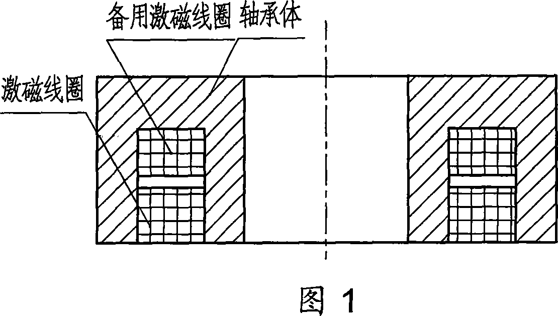
However, the existing axial magnetic bearing with redundant structure adopts active magnetic bearing structure, that is, two sets of excitation coils are wound in one bearing body to realize redundant structure. The schematic diagram of its structure is shown in Figure 1. When the coil fails, the other excitation coil can work normally. Due to the bias magnetic field generated by the passing current, there is a disadvantage of large power consumption.

Method used


Image

  • Low power consumption axial magnetic bearing with redundant structure
  • Low power consumption axial magnetic bearing with redundant structure
  • Low power consumption axial magnetic bearing with redundant structure

Examples


Embodiment Construction

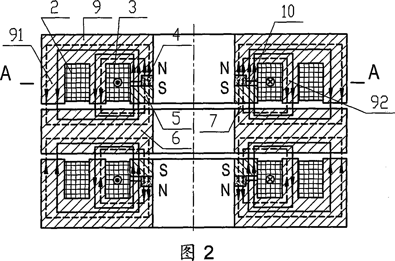
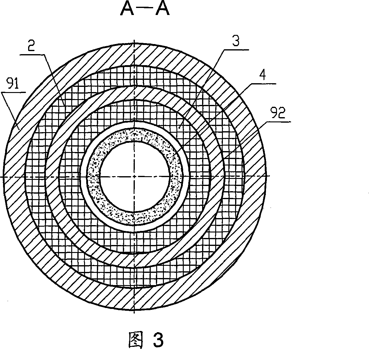
[0017] As shown in Fig. 2, Fig. 3 and Fig. 4, it is a low-power axial magnetic bearing with redundant structure, which is one of the technical solutions of the present invention, which is the basic form of the present invention. It consists of bearing body 9, excitation coils 2 and 3, permanent magnet 4, magnetic conduction ring 5, air gap 7, auxiliary air gap 10 and suspension body 6, permanent magnet 4 is closely attached to bearing body 9, magnetic conduction ring 5 It is closely attached to the permanent magnet 4 and forms an auxiliary air gap 10 with the bearing body 9 in the axial direction. The bearing body 9 includes an outer magnetic pole 91 and a middle magnetic pole 92. An air gap 7 is formed between them, and the permanent magnet 4 generates a bias magnetic flux in the air gap 7. Two sets of excitation coils 2 and 3 are wound in the bearing body 9, and the excitation coils 2 and 3 are used to generate control magnetic flux. The excitation coils 2, The permanent mag...


PUM


Abstract

A low power axial magnetic bearing with redundant structure is characterized in that it is composed of bearing body, exciting coils, permanent magnet, magnetic ring, air gap, auxiliary air gap and suspension body. The permanent magnet clings to the bearing body to generate bias flux, the magnetic ring clings to the permanent magnet and forms the auxiliary air gap with the bearing body, the air gap is formed among the magnetic ring, the bearing body pole and the suspension body to generate bias flux, the bearing body is winded with two groups of the exciting coils to generate control flux, the exciting coil, the permanent body and the magnetic ring are formed to redundant axial magnetic bearing stators relative to each other. The invention realizes the redundancy for the structure of the permanent bias axial magnetic bearing, prevents the electromagnetic magnetic path from passing the internal part of the permanent body, and reduces the exciting current. The invention has high reliability and low power consumption, and can work as non-contact support for the rotating components in the flywheel and other devices.

Description

technical field [0001] The invention relates to a non-contact magnetic suspension bearing, in particular to a low-power axial magnetic bearing with a redundant structure, which can be used in systems such as magnetic suspension flywheels, magnetic suspension control moment gyroscopes, aeroengines, molecular pumps, high-speed machine tools and satellites Contact-free support for rotating parts. Background technique [0002] Due to the advantages of non-contact, no lubrication, long life, low noise and high control precision, the magnetic suspension bearing can be widely used in aviation, aerospace and mechanical processing and other fields. In fields requiring high reliability such as aero-engines and spacecraft, in order to improve the reliability of the magnetic suspension bearing system, the magnetic suspension bearing system is required to have redundancy and fault tolerance functions. The permanent magnet bias axial magnetic bearing of the existing structure uses a perm...

Claims


Application Information

Patent Timeline
IPC IPC(8): F16C32/04
Inventor 韩邦成房建成刘刚孙津济
Owner BEIHANG UNIV
Learn More