
Eight-arm mechanical pusher

A pusher and mechanical technology, applied in measurement, wellbore/well parts, earthwork drilling and production, etc., can solve the problems of high manufacturing cost, affecting the accuracy of caliper measurement, and small measurement range, so as to improve reliability and stability Resilience, easy daily maintenance, easy centering effect

Active Publication Date: 2007-10-17
CHINA NAT OFFSHORE OIL CORP +1
View PDF1 Cites 28 Cited by
  • Summary
  • Abstract
  • Description
  • Claims
  • Application Information

AI Technical Summary

Problems solved by technology

Since the expansion and contraction of the pole plate is realized through a complete set of hydraulic system (including hydraulic motor, hydraulic pump, solenoid valve, etc.), the following defects inevitably exist: 1) The hydraulic system is complicated, the manufacturing cost is high and the maintenance is difficult; 2) The conductivity curve is limited by the number of plates, and the measurement range is small; 3) The caliper sampling signal is relatively small, which affects the accuracy of caliper measurement
[0005] The above-mentioned patented technology has many advantages such as wide applicable working range, but because the transmission of its mechanism is realized by using the motor to drive the piston in the hydraulic cylinder, not only the structure is complicated, but also the stability is very poor

Method used


Image

  • Eight-arm mechanical pusher
  • Eight-arm mechanical pusher
  • Eight-arm mechanical pusher

Examples


Embodiment Construction

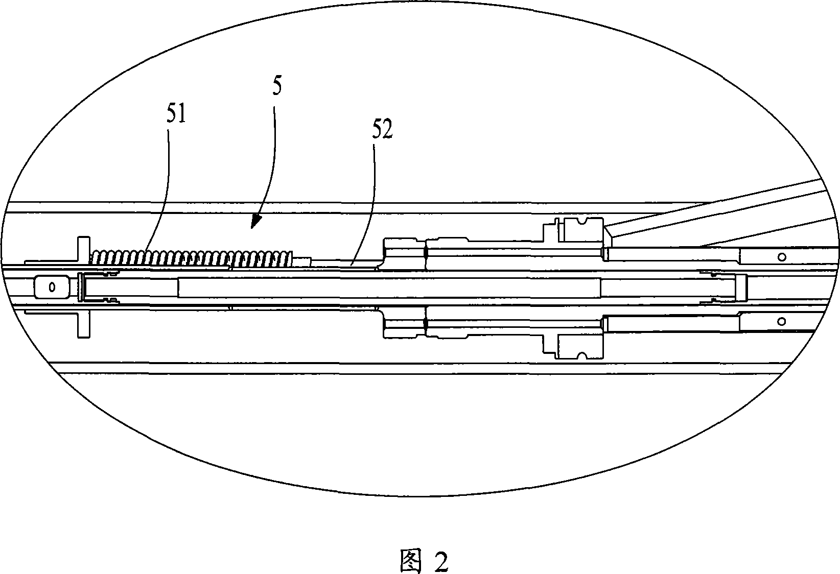
[0016] As shown in Figures 1 and 2, the present invention includes: a motor 1, a clutch 2, a roller screw 3, a transmission part 4, and eight pushing arms 6 arranged in the circumferential direction (only one is shown in Figure 1) ; The motor 1 is connected with the roller screw 3 through the clutch 2, and through the roller screw 3, the circumferential rotation displacement is converted into an axial displacement and then transmitted to the transmission part 4, and the transmission part 4 corresponds to 8 push arms 6 is provided with 8 elastic thrust mechanisms 5 (only one is shown in FIG. 1 ), and the 8 pushing arms 6 are opened or folded under the action of the elastic thrust mechanisms respectively.

[0017] The elastic thrust mechanism 5 includes a push spring 51 and a push rod 52 , one end of the push spring 51 presses against the transmission component 4 , and the other end is elastically connected to the push arm 6 through the push rod 52 . When opened, the motor 1 and...


PUM


Abstract

The invention discloses a mechanical eccentering arm with eight arms including a motor, a clutch, a roller threaded spindle, drive parts and an eccentering arm; the motor is connected to the roller threaded spindle by the clutch and is transferred to the drive parts by the roller threaded spindle after the circumference direction rotating displacement changes to the axial direction moving displacement, an elasticity thrust mechanism is arranged on the drive parts, the eccentering arm stretches out or folds up under the action of the elasticity thrust mechanism. The invention has advantages of simple and reasonable structure, convenient maintenance and high reliability and so on.

Description

technical field [0001] The invention relates to a pushing device used on a petroleum well logging instrument. Background technique [0002] The pusher is an important part of the oil well logging inclination instrument. When the inclination logging instrument moves in the well, the pusher uses sufficient pressure to make the electrode plates on each arm stick to the well wall, and make the opposite electrodes and the instrument The axes maintain a fixed distance. Each electrode records a micro-focused conductivity curve, so as to calculate the real dip and dip of the formation. [0003] At present, dip logging tools commonly used in oil well logging include four-arm or six-arm dip logging tools, and the components of their pusher parts are the same. Since the expansion and contraction of the pole plate is realized through a complete set of hydraulic system (including hydraulic motor, hydraulic pump, solenoid valve, etc.), the following defects inevitably exist: 1) The hydr...

Claims


Application Information

Patent Timeline
Patent Type & Authority Applications(China)
IPC IPC(8): E21B47/02
Inventor 冯永仁卢涛李军张勇
Owner CHINA NAT OFFSHORE OIL CORP
Learn More