Eureka AIR delivers breakthrough ideas for toughest innovation challenges, trusted by R&D personnel around the world.

Outer rotor fan type biological safety cabinet

A technology of external rotor fan and biological safety cabinet, which is applied in the direction of heating method, ventilation system, shell or chamber, etc., which can solve the problems of non-adjustable pedals, difficulty in negative pressure surrounding, uneven airflow, etc., and achieve improved cleanliness and laminar flow uniformity, maintaining uniform stability, and laminar flow uniformity and stability

Inactive Publication Date: 2007-10-17
李晨
View PDF0 Cites 12 Cited by
  • Summary
  • Abstract
  • Description
  • Claims
  • Application Information

AI Technical Summary

Problems solved by technology

[0002] In the existing biological safety cabinets, the fans of the core part use traditional centrifugal fans, so that the whole structure must be designed around its cumbersome shape. 2. Due to the limitation of large shape and easy vibration, it is not easy to solve the problem of filter sealing structure, and often cannot guarantee strict sealing performance. Small leakage will directly enter the clean working area of ​​the biological safety cabinet, which will affect the cleanliness; 3. Restricted by the structure, it is inconvenient to replace the high-efficiency filter; 4. The operation of the centrifugal fan is unstable and the service life is short; 5. Due to the limitation of the shape, it is difficult to form a negative pressure around the periphery of the operating area; 6. The bracket is heavy, and the height of the bracket itself can be adjusted Limited, the pedals are generally not adjustable, unable to meet the user's requirements for comfort and many other deficiencies

Method used


Image

  • Outer rotor fan type biological safety cabinet
  • Outer rotor fan type biological safety cabinet
  • Outer rotor fan type biological safety cabinet

Examples


Embodiment Construction

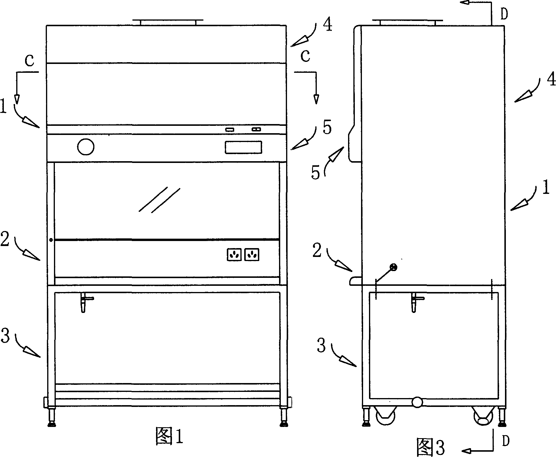
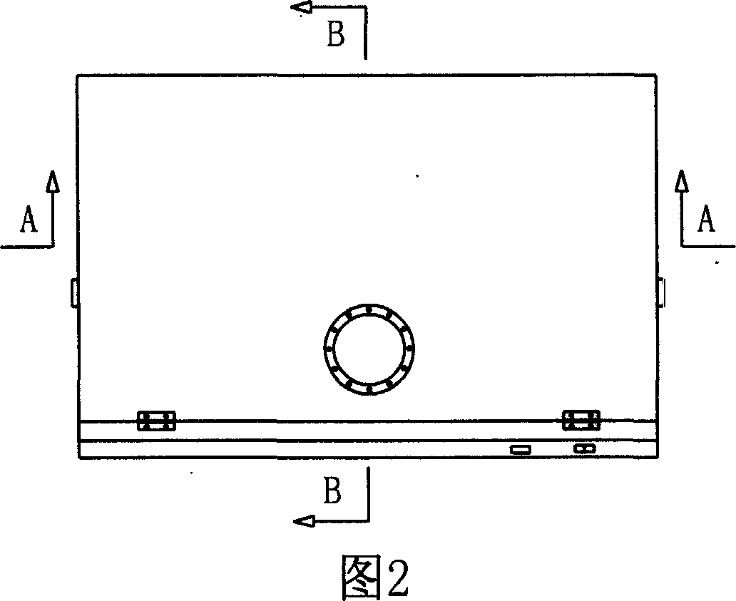
[0037] Referring to Fig. 1, Fig. 2 and Fig. 3, an external rotor fan type biological safety cabinet mainly consists of a cabinet body part 1, an operating table part 2, a support part 3, a purification work area part 4, a control part 5 and other components Composition; the cabinet part 1 is set on the bracket part 3, connected by hexagon socket bolts, in the cabinet part 1, the upper part is the purification work area part 4, the lower part is the operation table part 2, and the control part 5 is located in the purification work area part The inside of 4 is installed on the front of the cabinet body part 1 to facilitate the operation of personnel by relevant electrical appliances and circuit wires.

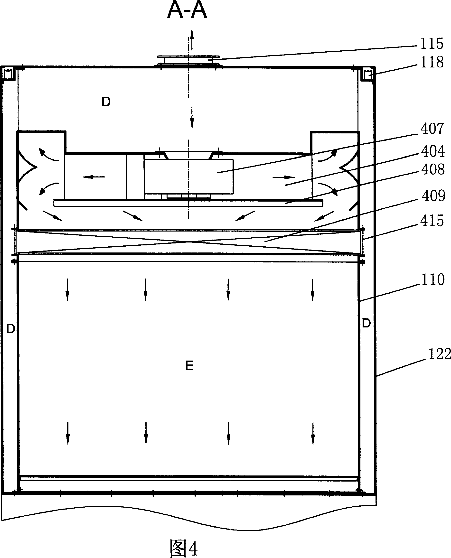
[0038] Referring to Fig. 4, Fig. 5, and Fig. 6, the cabinet part 1 includes a front panel 101, a counterweight steel wire 102, a front baffle 103, a front beam 104, a lifting glass 105 with a handle, a front column 106, Lifting glass trough 107, rear column 108, console back pane...


PUM


Abstract

The invention relates to an outer rotor fan style bio-safety cabinet, which cabinet body part is arranged on a bracket part. An upper part of the cabinet body part is cleaning work area, and an lower part is an operating part. A control part is arranged on front of the cabinet body part via relative electric appliances and circuit, an air supply filter of the cleaning work area is arranged on a I-shaped bracket, and an air supply plenum box is arranged on the air supply filter compressed sealed by an upper and lower faces . The I-shaped bracket and the air supply plenum box are pressed on the air supply filter, the central part is positioned on a zone of negative pressure. The air supply plenum box is provided with a baffle, an anechoic guide vane, and an outer rotor fan, and an air exhausting filter and an air exhausting plenum box pressing tightly on the air exhausting filter are arranged above the air supply plenum box. The invention can effectively increase cleanliness and laminar flow uniformity and regulate ratio size of air volume flowing through a front and a bock return air inlets, and the invention has advantages of stable operation, reliable seal and low noise.

Description

technical field [0001] The invention belongs to the field of purification equipment and relates to an outer rotor fan type biological safety cabinet used for biological experiment operations. Background technique [0002] In the existing biological safety cabinets, the fans of the core part use traditional centrifugal fans, so that the whole structure must be designed around its cumbersome shape. 2. Due to the limitation of large shape and easy vibration, it is not easy to solve the problem of filter sealing structure, and often cannot guarantee strict sealing performance. Small leakage will directly enter the clean working area of ​​the biological safety cabinet, which will affect the cleanliness; 3. Restricted by the structure, it is inconvenient to replace the high-efficiency filter; 4. The operation of the centrifugal fan is unstable and the service life is short; 5. Due to the limitation of the shape, it is difficult to form a negative pressure around the periphery of t...

Claims


Application Information

Patent Timeline
IPC IPC(8): B01L1/00F24F7/06
Inventor 李晨
Owner 李晨
Why Eureka
Eureka Blog
Learn More