Eureka AIR delivers breakthrough ideas for toughest innovation challenges, trusted by R&D personnel around the world.

Convection part for electric oven range

a technology of convection part and oven cavity, which is applied in the direction of ovens, stoves or ranges, heating types, etc., can solve the problems of unfavorable heat distribution in the oven cavity, inconvenient convection part discharge, and small size of air outlets, so as to achieve smooth flow, reduce time, and increase efficiency

Inactive Publication Date: 2008-02-12
LG ELECTRONICS INC
View PDF9 Cites 18 Cited by
  • Summary
  • Abstract
  • Description
  • Claims
  • Application Information

AI Technical Summary

Benefits of technology

The present invention is a convection part of an electric oven range that improves airflow for smoother cooking. It includes a convection motor, a convection fan, and a fan housing with discharge ducts. The convection part can circulate air and discharge it through the discharge ducts, resulting in a more uniform cooking of food and increased efficiency. Overall, the invention allows for faster and more effective cooking in the oven.

Problems solved by technology

However, since the convection part includes a plurality of air outlets around the outer wall of the convection part, the sizes of the air outlets are relatively small.
Thus, air is not smoothly discharged from the convection part through the small air outlets.
This decreases heat convection in the oven cavity to cause non-uniform heat distribution in the oven cavity.
Therefore, food is heated non-uniformly and more time is required to cook food.

Method used


Image

  • Convection part for electric oven range
  • Convection part for electric oven range
  • Convection part for electric oven range

Examples


Embodiment Construction

[0024]Reference will now be made in detail to the preferred embodiments of the present invention, examples of which are illustrated in the accompanying drawings.

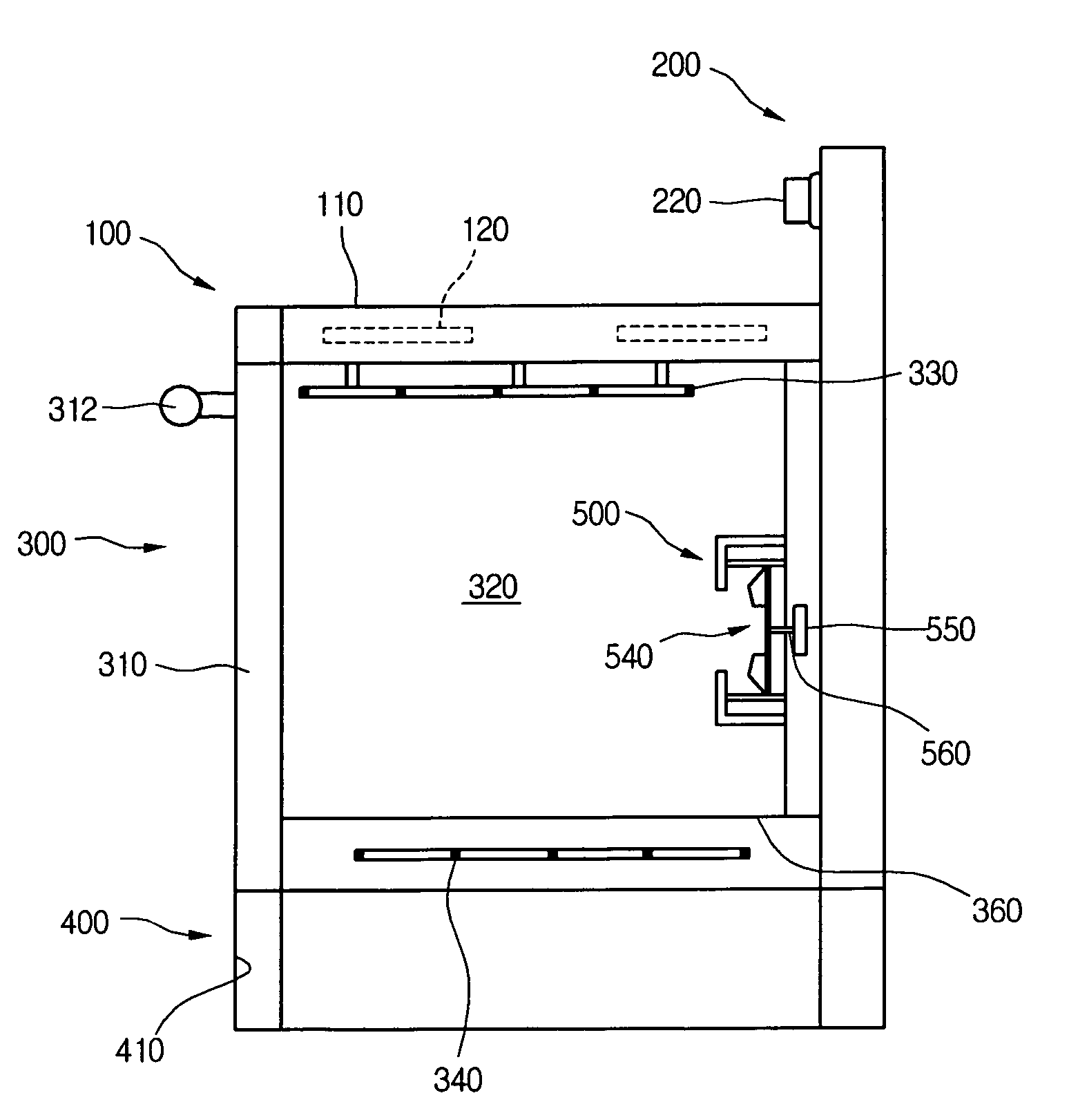
[0025]FIG. 1 is a perspective view of an electric oven range employing a convection part according to the present invention.

[0026]Referring to FIG. 1, an electric oven range includes a top burner part 100 on a top to cook food in a general way. A food container filled with food is placed on a burner (described below) of the top burner part 100, and heat is radiated from the burner 120 to the food container. The radiated heat is conducted through the food container to the food to cook the food. When cooking food using the top burner part 100, cooking state of the food can be easily seen.

[0027]The top burner part 100 includes a top plate 110 on a top surface. The top plate 110 is made of ceramic material to resist high temperatures, and it covers the top surface of the burner part 100. Also, the top burner part 100 includes a ...


PUM


Abstract

A convection part of an electric oven range is provided. In the convection part, a convection motor is provided, a convection fan is connected with the convection motor, and a fan housing encloses the convection fan and it includes at least one pair of discharge ducts in opposite directions.

Description

BACKGROUND OF THE INVENTION[0001]1. Field of the Invention[0002]The present invention relates to an electric oven range, and more particularly, to a convection part for an electric oven range.[0003]2. Description of the Related Art[0004]An electric oven range is a cooking device that has a plurality of heaters generating heat from electricity to cook food. An electric oven range is a kind of a combined kitchen appliance that includes an oven function for cooking food in a closed space using heat generated from a heater and a range function for cooking food by applying heat directly to a food container placed on a top surface.[0005]Electric oven ranges can heat both the inside and outside of food, such that they can cook food faster than gas oven ranges. Also, since electric oven ranges use electricity to generate heat, they provide a safer way of cooking and higher efficiency in using generated heat. Therefore, electric oven ranges are being more widely used.[0006]An electric oven r...

Claims


Application Information

Patent Timeline
Patent Type & Authority Patents(United States)
IPC IPC(8): A21B1/00
CPCF24C15/322F24C15/325
Inventor SONG, SUNG HOLEE, SANG IKEOM, YOON SEOBKIMCHOI, MOO YEON
Owner LG ELECTRONICS INC
Why Eureka
Eureka Blog
Learn More