Structure of reducer container

A reducing agent and container technology, which is applied in the structural field of reducing agent containers, can solve the problems that the concentration meter and the box-shaped member cannot be combined without gaps, and the concentration detection accuracy is reduced, so as to suppress the change of heat transfer characteristics and improve the detection accuracy. Accuracy, effect of promoting thawing

Inactive Publication Date: 2007-10-10
UD TRUCKS CORP
View PDF1 Cites 13 Cited by
  • Summary
  • Abstract
  • Description
  • Claims
  • Application Information

AI Technical Summary

Problems solved by technology

Once air bubbles adhere to the detection part of the concentration meter, the heat transfer characteristics between the two separated points will change, and the concentration detection accuracy will be greatly reduced.
In addition, the concentration meter requires regular maintenance, so the concentration meter and the box-shaped member cannot be combined without gaps

Method used


Image

  • Structure of reducer container
  • Structure of reducer container
  • Structure of reducer container

Examples


Embodiment Construction

[0032] The present invention will be described in detail below with reference to the accompanying drawings.

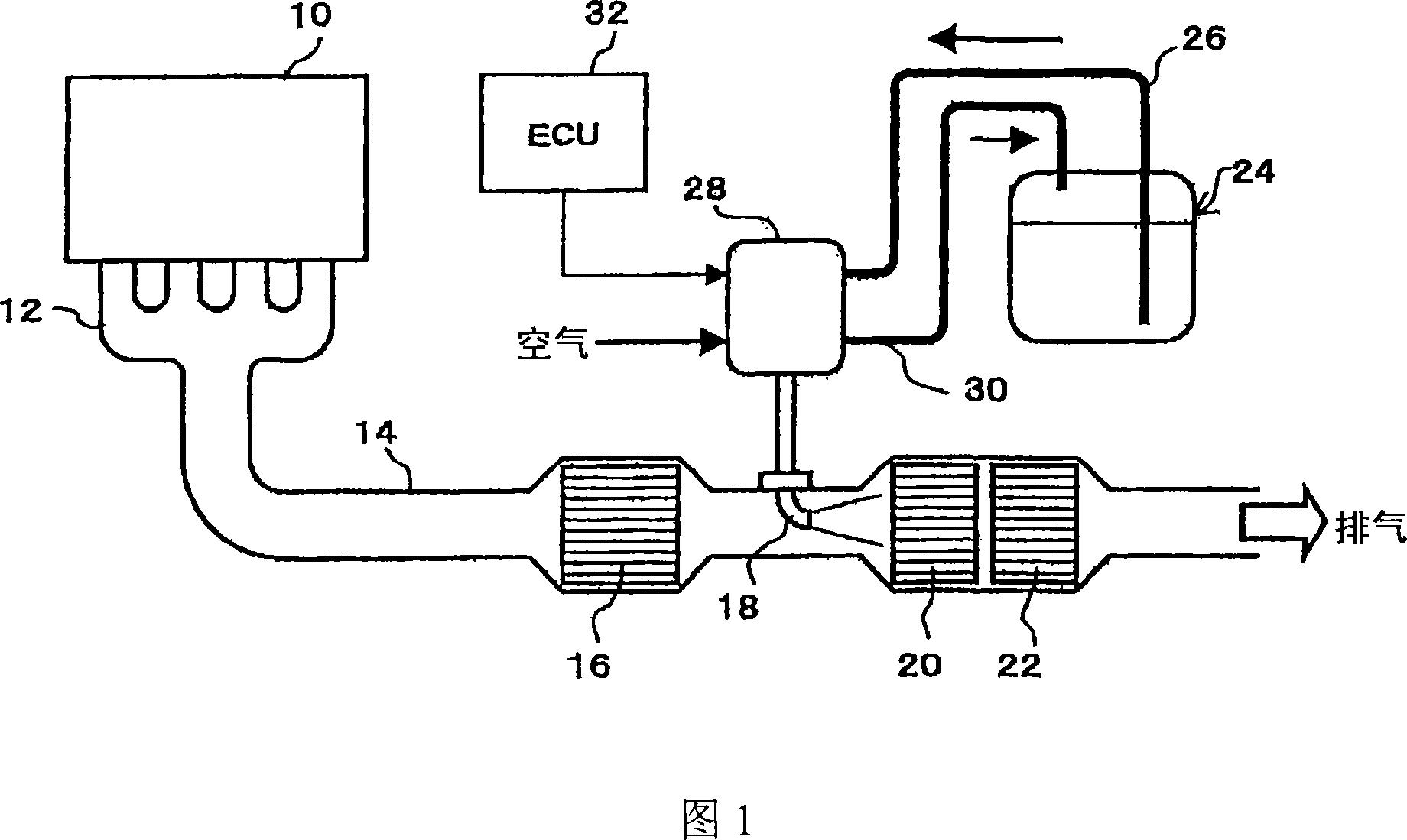
[0033] FIG. 1 shows the overall structure of an exhaust gas purification device, which uses urea aqueous solution as a liquid reducing agent to purify NOx in engine exhaust gas through a catalytic reduction reaction.

[0034] In FIG. 1 , on the exhaust pipe 14 connected to the exhaust manifold 12 of the engine 10, along the exhaust flow direction, there are respectively arranged: nitrogen monoxide (NO) is oxidized to nitrogen dioxide (NO 2 ) oxidation catalyst 16; nozzle 18 for spraying and supplying urea aqueous solution; NOx reduction catalyst 20 for reducing and purifying NOx with ammonia obtained by hydrolyzing urea aqueous solution; ammonia oxidation catalyst 22 for oxidizing ammonia passing through NOx reduction catalyst 20 . In addition, the urea aqueous solution stored in the reducing agent container 24 is supplied to the reducing agent supply device 28 throug...


PUM


Abstract

A structure of a reducer container, wherein at least the base part of a concentration meter detecting the concentration of a liquid reducer from temperature transmission characteristics across two points apart from each other and a heat exchanger performing heat exchange with the liquid reducer by circulating an engine cooling water while surrounding a detection part suspended from the base part of the concentration meter through columns are mounted on the upper surface of a container body. Also, a roughly box-shaped protector is disposed so as to surround the lower part of the heat exchanger and the detection part of the concentration meter, and a visor is mounted on the columns of the concentration meter located at an upper position apart a specified distance from the protector.

Description

technical field [0001] The present invention relates to a technique for promoting thawing of a liquid reductant stored in a reductant container in an exhaust gas purification device for reducing and purifying nitrogen oxides (NOx), and improving the flow rate from two separated points. The heat transfer characteristic detects the detection accuracy of the concentration meter of the liquid reducing agent concentration. Background technique [0002] As a catalytic purification system for removing NOx in exhaust gas of an engine, an exhaust purification device disclosed in JP 2000-27627 A (Patent Document 1) has been proposed. This exhaust purification device injects and supplies a liquid reductant corresponding to the operating state of the engine to the upstream of the reduction catalyst provided in the exhaust system of the engine, so that the NOx in the exhaust gas and the liquid reductant undergo a catalytic reduction reaction, and the NOx ...

Claims


Application Information

Patent Timeline
Patent Type & Authority Applications(China)
IPC IPC(8): F01N3/08F01N3/24F01N3/20
CPCF01N2610/02F01N2610/10F01N2610/148F01N2610/1486Y02T10/24F01N2900/1814F01N3/2066F01N2900/1818F01N2610/1406Y02T10/12
Inventor 仁科充广松永英树井上真一中村利美
Owner UD TRUCKS CORP
Why Eureka
Try Eureka